Cable connector
A technology of cable connectors and discharge resistors, which is applied in the direction of connection and connection device components, circuits, etc., can solve the problems of short circuit of connectors, weak waterproof ability, inconvenient fast plugging and unplugging of cables, etc., so as to avoid falling off and facilitate carrying effect
- Summary
- Abstract
- Description
- Claims
- Application Information
AI Technical Summary
Problems solved by technology
Method used
Image

Examples
Embodiment 1
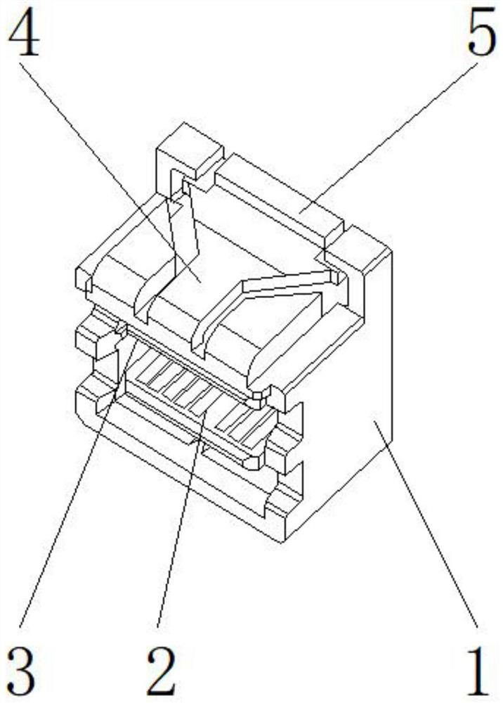
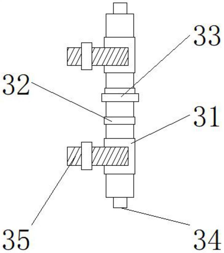
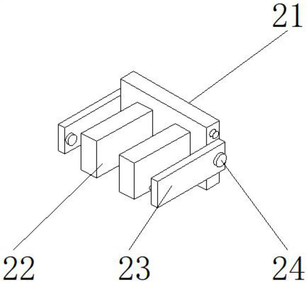
[0030] like Figure 1-6 As shown, the present invention provides a cable connector, including a main body 1, the inner side of the main body 1 is provided with a convenient plugging mechanism 2, an anti-pulling arc device 3 is provided above the convenient plugging mechanism 2, and the upper end of the main body 1 is provided with a The anti-opening alarm device 4 is provided with a waterproof device 5 on one side of the anti-opening alarm device 4; On the surface, the rocker arms 223 are located on both sides of the bottom plate 21, and the torsion spring 24 is located on one side of the rocker arm 23; One side of the base plate 22 is detachably connected, a welding block is provided between the partition plate 22 and the bottom plate 21, the front end of the bottom plate 21 is fixedly connected to the rear end of the partition plate 22 through the welding block, and a movable bolt is provided between the bottom plate 21 and the rocker arm 23, One side of the rocker arm 23 i...
Embodiment 2
[0033] like Figure 1-6 As shown, on the basis of Embodiment 1, the present invention provides a technical solution: preferably, the anti-opening alarm device 4 includes a sampling module 41, a sampling signal processing module 42, a monitoring display processing module 43, and an alarm processing module 44. The signal processing module 42 is located at the upper end of the sampling module 41, the monitoring display processing module 43 is located at the upper end of the sampling signal processing module 42, the alarm processing module 44 is located at the lower end of the sampling module 41, and a sensor is provided between the sampling module 41 and the sampling signal processing module 42. , the input end of the sampling signal processing module 42 is signally connected to the output end of the sampling module 41 through the sensor, a wire is provided between the sampling signal processing module 42 and the monitoring display processing module 43, and the output end of the s...
Embodiment 3
[0036] like Figure 1-6 As shown, on the basis of Embodiment 1, the present invention provides a technical solution: preferably, the waterproof device 5 includes a cable 51, a locking nut 52, a waterproof ring 53, a waterproof washer 54, a connector shell 55, and a cable 51. 51 runs through the inner wall of the lock nut 52, the waterproof ring 53 is located on one side of the lock nut 52, the connector shell 55 is located on one side of the waterproof ring 53, the waterproof gasket 54 is located on one side of the connector shell 55, and the waterproof ring 53 is located on the side of the waterproof ring 53. A strong glue is arranged between the locking nuts 52, one side of the waterproof ring 53 is fixedly connected to one side of the locking nut 52 through the strong glue, a connecting hole is provided between the cable 51 and the locking nut 52, and the locking nut 52 The inner wall of the cable 51 is fixedly connected to the outer wall of the cable 51 through the connect...
PUM
 Abstract
Description
Claims
Application Information
 - Generate Ideas
- Intellectual Property
- Life Sciences
- Materials
- Tech Scout
- Unparalleled Data Quality
- Higher Quality Content
- 60% Fewer Hallucinations
Browse by: Latest US Patents, China's latest patents, Technical Efficacy Thesaurus, Application Domain, Technology Topic, Popular Technical Reports.
© 2025 PatSnap. All rights reserved.Legal|Privacy policy|Modern Slavery Act Transparency Statement|Sitemap|About US| Contact US: help@patsnap.com