
Three-phase combined transformer

A combined transformer and transformer technology, applied in the field of transformer manufacturing, can solve the problem that the large-capacity integrated transformer cannot meet the transportation conditions in remote mountainous areas, etc., and achieve the effect of ensuring the quality of on-site installation, reducing the workload, and ensuring the amount of adjustment

Pending Publication Date: 2022-06-03
BAODING TIANWEI BAOBIAN ELECTRICAL
View PDF0 Cites 0 Cited by
  • Summary
  • Abstract
  • Description
  • Claims
  • Application Information

AI Technical Summary

Problems solved by technology

[0005] In order to make up for the deficiencies of the existing technology and solve the problem that the existing large-capacity integrated transformer is difficult to meet the harsh transportation conditions in remote mountainous areas, the present invention proposes a three-phase combined transformer

Method used


Image

  • Three-phase combined transformer
  • Three-phase combined transformer
  • Three-phase combined transformer

Examples


Embodiment 1

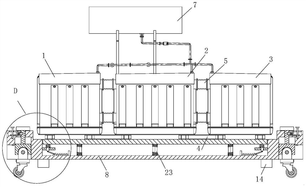
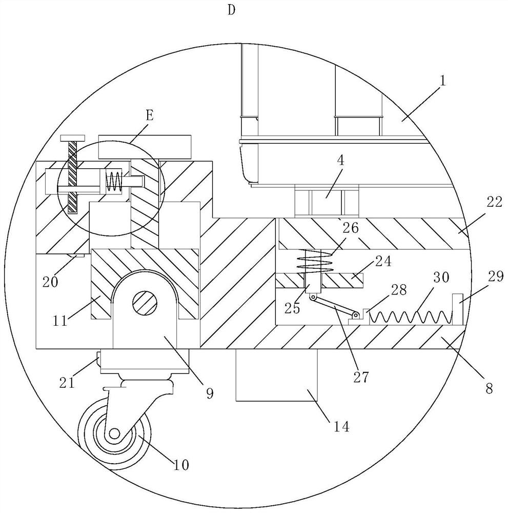
[0028] see Figure 1-6As shown, a three-phase combined transformer includes an A-phase transformer 1, a B-phase transformer 2 and a C-phase transformer 3; the bottoms of the A-phase transformer 1, B-phase transformer 2 and C-phase transformer 3 are all fixed with steel chassis 4; a bellows 5 is fixedly connected between the A-phase transformer 1 and the B-phase transformer 2, and the bellows 5 is provided with a lead wire, so that the B-phase transformer 2 and the C-phase transformer 3 are electrically connected; the A bellows 5 is also fixed between the B-phase transformer 2 and the C-phase transformer 3, and the bellows 5 is provided with a lead wire, so that the B-phase transformer 2 and the C-phase transformer 3 are electrically connected; A three-phase integrated on-load tap-changer 6 is provided; an oil conservator 7 is fixed on the top of the B-phase transformer 2, and the oil conservator 7 is connected to the interior of the A-phase transformer 1, B-phase transformer 2...

Embodiment 2

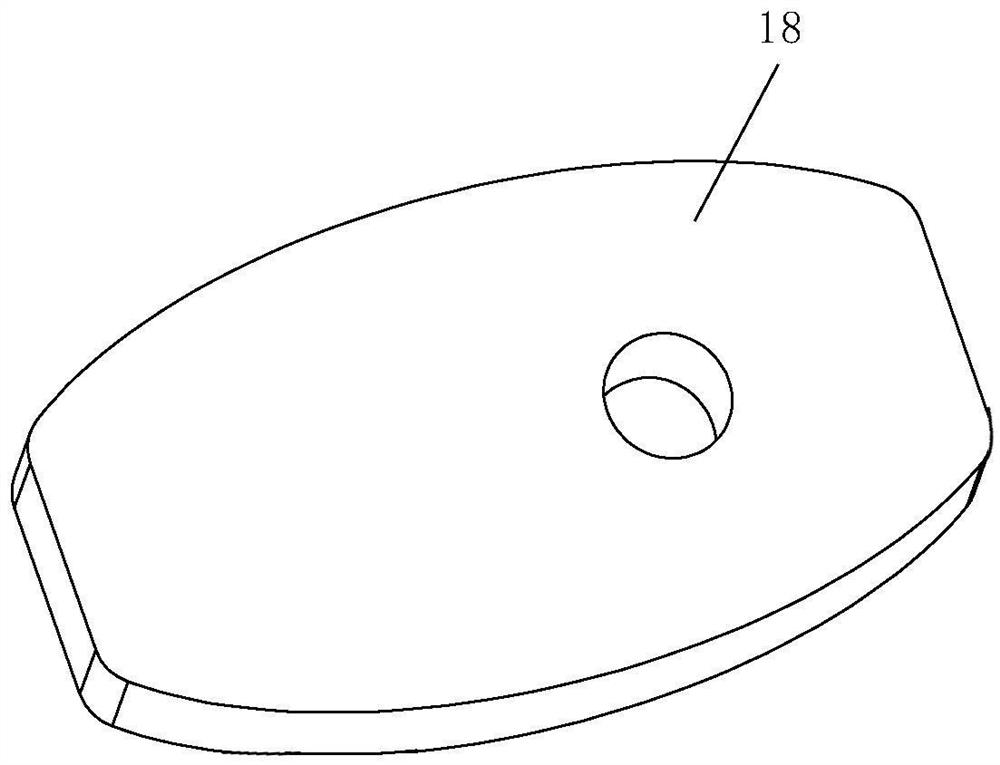
[0037] see Figure 7 As shown in Comparative Example 1, as another embodiment of the present invention, a handle 31 is fixed to the top of the threaded rod 17; during operation, the handle 31 is provided to facilitate the rotation of the threaded rod 17. When the rod 17 rotates downward, it will make the cam 18 squeeze the No. 2 plate 15 to realize the fixation of the No. 1 rod 12. When the threaded rod 17 rotates upward, it will make the cam 18 leave the No. 2 plate 15, so as to realize the fixing of the No. 1 rod 12. Reset of the second lever 16.

[0038] Working principle: In order to facilitate the movement of the three-phase transformer, a jack can be used at the bottom of the base and raised a certain distance, and then the universal wheel 10 is rotated so that the wheel of the universal wheel 10 is in contact with the ground. Push down the push plate 13, so that the push plate 13 drives the No. 1 rod 12 and the positioning block 11 to move downward, so that the top of ...


PUM


Abstract

The invention relates to the technical field of transformer manufacturing, in particular to a three-phase combined transformer which comprises an A-phase transformer, a B-phase transformer and a C-phase transformer. The bottoms of the A-phase transformer, the B-phase transformer and the C-phase transformer are fixedly connected with steel underframes; a corrugated pipe is fixedly connected between the A-phase transformer and the B-phase transformer, and a lead is arranged in the corrugated pipe, so that the B-phase transformer and the C-phase transformer are electrically connected; a corrugated pipe is also fixedly connected between the B-phase transformer and the C-phase transformer; according to the invention, the three-phase integrated on-load tap-changer is reasonably arranged, the arrangement mode of leads is improved, the workload of lead channels and field installation is reduced, and the internal insulation performance and the field installation quality of the transformer are ensured; the corrugated pipe and the integral steel underframe are reasonably arranged, so that the adjusting quantity of field installation is ensured, and the installation error is avoided; the transformer is small in on-site occupied area and light in transportation weight.

Description

technical field [0001] The invention relates to the technical field of transformer manufacturing, in particular to a three-phase combined transformer. Background technique [0002] A three-phase transformer is a large-scale power distribution equipment that uses the principle of electromagnetic induction to adjust the output voltage. [0003] The existing three-phase transformer is generally composed of a primary coil, a secondary coil and an iron core, and the volume is relatively large. [0004] With the growth of power demand in remote mountainous areas, the required capacity of power transformers also increases, and the existing large-capacity integrated transformers are difficult to meet the harsh transportation conditions in remote mountainous areas. Therefore, a three-phase combination is proposed to solve the above problems. type transformer. SUMMARY OF THE INVENTION [0005] In order to make up for the deficiencies of the prior art and solve the problem that the...

Claims


Application Information

Patent Timeline
IPC IPC(8): H01F27/06H01F27/14H01F27/29
CPCH01F27/06H01F27/14H01F27/29
Inventor 兰洪顺赵永杰刘荣田小静崔轶刘洁焦玉龙刘会召杜君妮王云鹏张建彬赵延涛王岩
Owner BAODING TIANWEI BAOBIAN ELECTRICAL
Learn More