
Radiation impact target and method for generating radiation impact waves with speed of more than 100km/s in xenon

A technology of shock wave and shock target, which is applied in the field of high energy density physics, can solve the problems that it is difficult to obtain radiation shock wave front images, etc., and achieve the effect of low cost, simple steps and simple structure

Pending Publication Date: 2022-06-03
LASER FUSION RES CENT CHINA ACAD OF ENG PHYSICS
View PDF7 Cites 0 Cited by
  • Summary
  • Abstract
  • Description
  • Claims
  • Application Information

AI Technical Summary

Problems solved by technology

However, some existing radiation shock targets cannot generate 100 high-speed radiation shock waves in xenon gas after the shock target is filled with xenon gas, so it is difficult to obtain radiation shock wave front images with obvious contrast

Method used


Image

  • Radiation impact target and method for generating radiation impact waves with speed of more than 100km/s in xenon
  • Radiation impact target and method for generating radiation impact waves with speed of more than 100km/s in xenon
  • Radiation impact target and method for generating radiation impact waves with speed of more than 100km/s in xenon

Examples


Embodiment 1

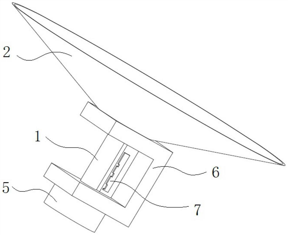
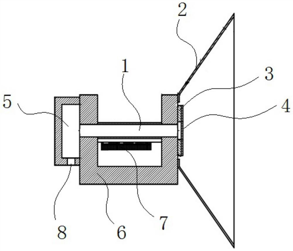
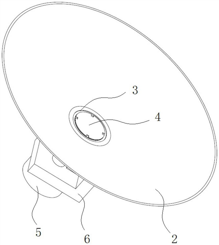
[0030] like Figure 1 to Figure 3 As shown, a radiation impact target includes a shock wave tube 1, a shielding cover 2, an annular metal sheet 3, an ablation layer 4, and a gas storage chamber 5; one end of the shock wave tube 1 is communicated with the gas storage chamber 5, and the other One end is communicated with one end of the shielding cover 2, and the other end of the shielding cover 2 is open; the annular metal sheet 3 is arranged on one end of the shock wave tube 1 connected with the shielding cover 2, and the ablation layer 4 is arranged on the annular metal sheet 3. on slice 3. The nanosecond laser is loaded on the ablation layer 4, and the heated material scatters backward, generating a forward driving force, and driving the remaining material to compress the xenon gas in the shock wave tube 1 inward, and its function is to generate a propagating into the shock wave tube 1. shock wave. The ring-shaped metal sheet 3 filters the X-rays on the target surface of th...

Embodiment 2

[0038] The other structures of this embodiment are the same as those of Embodiment 1. The difference is that it also includes a support member 6 for preventing the deformation of the shock wave tube 1 , and the support member 6 is sleeved on the shock wave tube 1 . Because the shock wave tube 1 has a thin and long wall and is composed of organic materials, it cannot be self-supporting, and an organic support structure is required to ensure that its structure remains unchanged; in this embodiment, a support member 6 is provided on the shock wave tube 1 to support the shock wave tube 1 . The protection function prevents the shock wave tube 1 from being deformed after receiving the action of the shock wave.

Embodiment 3

[0040] This embodiment provides a method for generating a radiation shock wave with a velocity of more than 100 km / s in xenon gas, using the shooting shock target described in Embodiment 1, which specifically includes the following steps:

[0041] Charge 1-2 atm of xenon gas into the gas storage chamber 5 communicated with the shock wave tube 1 through the gas charging tube;

[0042] Four nanosecond laser beams with an energy of 1.6kJ~3.2kJ, a spot diameter of 650μ~740μm, a pulse of 0.5ns~1.5ns, and a wavelength of 0.3μm~0.4μm are used to act on the ablation layer 4, nanosecond laser Loaded on the ablation layer 4, the heated material scatters backward, generating a forward driving force, driving the remaining material to compress the xenon gas in the shock wave tube 1 inward, and generating a shock wave propagating into the shock wave tube 1;

[0043] like Figure 4 As shown, the shock wave front image at a certain moment is obtained by using X-ray fluorophotography; the rad...


PUM

PropertyMeasurementUnit
Wall thicknessaaaaaaaaaa
Lengthaaaaaaaaaa

Abstract

The invention relates to the technical field of high-energy density physics, in particular to a radiation impact target and a method for generating radiation impact waves with the speed of 100 km / s or above in xenon. The radiation impact target comprises an impact wave tube, a shielding cover, an annular metal sheet, an ablation layer and a gas storage chamber, one end of the shock wave tube is communicated with the gas storage chamber, the other end of the shock wave tube is communicated with one end of the shielding case, and the other end of the shielding case is open; the annular metal sheet is arranged at the end part of one end, connected with the shielding cover, of the shock wave tube, and the ablation layer is arranged on the annular metal sheet. The ablation layer acts with the nanosecond laser, and radiation shock waves are generated in the shock wave tube filled with xenon. The X-ray fluoroscopic photography technology can be used for carrying out fluoroscopic photography on the radiation shock wave propagation process. The propagation velocity of the radiation shock wave can be obtained through the relative position of the radiation shock wave wavefront and the positioning grid and the relative delay of the X-ray source and the nanosecond laser pulse.

Description

technical field [0001] The invention relates to the technical field of high energy density physics, and more particularly, to a radiation shock target and a method for generating radiation shock waves with a velocity of over 100 km / s in xenon gas. Background technique [0002] Radiation shock waves widely exist in celestial systems such as supernova explosions, young stars, catastrophic variables and black holes. Different from ordinary shock waves, radiation shock waves are characterized in that radiation transport affects the hydrodynamic evolution process of shock waves to a large extent. Radiation transport is highly coupled with hydrodynamic processes, so that the generation and propagation of radiation shock waves contain extremely rich physical phenomena. Carrying out experiments in the laboratory to study the evolution law of radiation shock waves can help human beings to understand related celestial phenomena, thereby deepening human understanding of the universe. ...

Claims


Application Information

Patent Timeline
IPC IPC(8): G01N23/04
CPCG01N23/04Y02E30/10
Inventor 张璐郑建华张帅魏胜景龙飞况龙钰杨正华袁永腾杨品杨家敏
Owner LASER FUSION RES CENT CHINA ACAD OF ENG PHYSICS
Learn More