Combined type hydraulic flow control valve

A flow control valve, compound technology, applied in the direction of lift valve, valve device, valve details, etc., can solve the problem of large valve plate blocking area, etc., to achieve the effect of improving applicability, avoiding relative rotation, and high precision

Active Publication Date: 2022-06-03
江苏菲尔特液压机械有限公司
View PDF10 Cites 0 Cited by
  • Summary
  • Abstract
  • Description
  • Claims
  • Application Information

AI Technical Summary

Problems solved by technology

[0005]The object of the present invention is to provide a composite hydraulic flow control valve to solve the problem that the valve plate in the existing valve has a large blocking area and cannot meet the requirements of the liquid at the same time. Technical Issues of Coarse and Fine Tuning of Flow

Method used

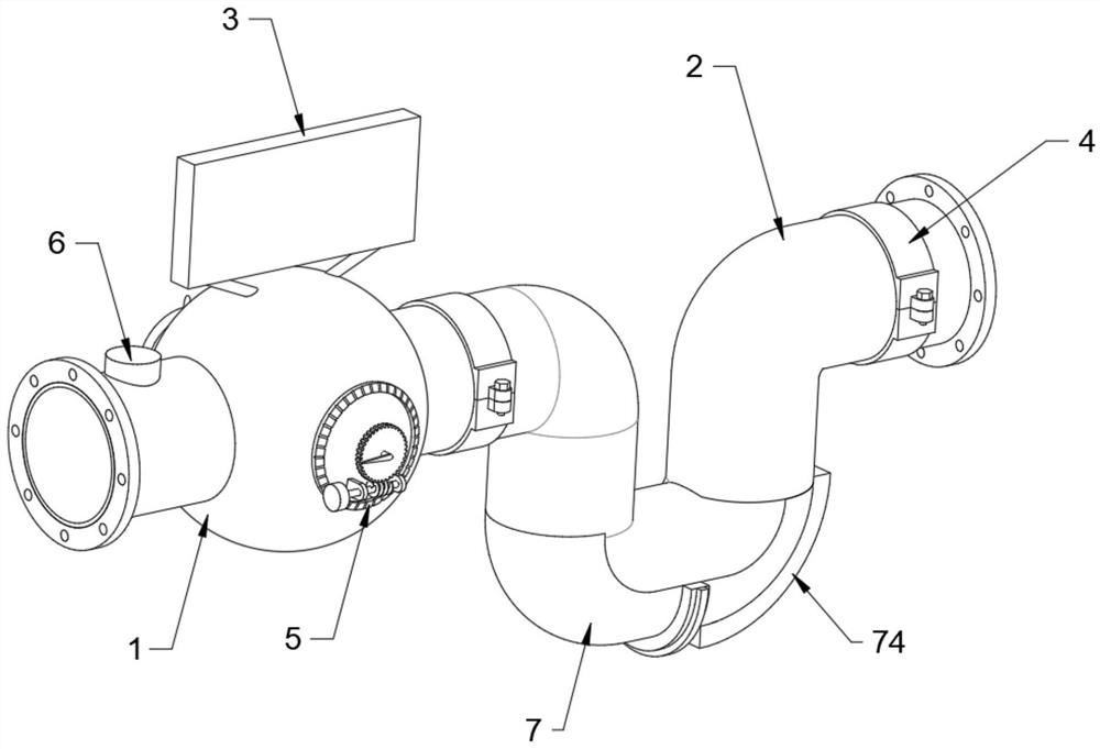
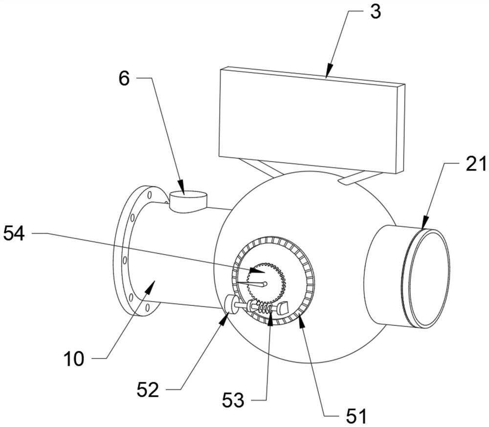
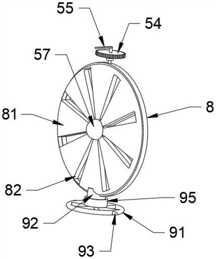

Image

  • Combined type hydraulic flow control valve
  • Combined type hydraulic flow control valve
  • Combined type hydraulic flow control valve

Examples


Embodiment Construction

[0034] The technical solutions of the present invention will be clearly and completely described below with reference to the accompanying drawings. Obviously, the described embodiments are a part of the embodiments of the present invention, but not all of the embodiments.

[0035] The components of the embodiments of the invention generally described and shown in the drawings herein may be arranged and designed in a variety of different configurations. Thus, the following detailed description of the embodiments of the invention provided in the accompanying drawings is not intended to limit the scope of the invention as claimed, but is merely representative of selected embodiments of the invention.

[0036] Based on the embodiments of the present invention, all other embodiments obtained by those of ordinary skill in the art without creative efforts shall fall within the protection scope of the present invention.

[0037]In the description of the present invention, it should be...


PUM


Abstract

The invention discloses a combined type hydraulic flow control valve and relates to the technical field of flow control valves, the combined type hydraulic flow control valve comprises a valve body and a water inlet pipe, an adjusting valve plate is arranged on one side of a reference valve plate, a fine adjustment mechanism is arranged on one side of the valve body, and a coarse adjustment mechanism is arranged on the other side of the valve body; butt joint structures are arranged at the two ends of the water inlet pipe, the water inlet pipe is connected with the valve body through the butt joint structures, a flow monitoring mechanism is arranged on the inner wall of the water outlet pipe, and an impurity collecting assembly is arranged on the inner wall of the water inlet pipe. When liquid needs to be subjected to large-flow circulation, the rotating disc is rotated, the convex rod is observed to rotate by a certain angle, the flow of the liquid is the maximum when the convex rod rotates by 90 degrees, and the fine adjustment mechanism and the coarse adjustment mechanism are arranged on one valve at the same time, so that the valve body can meet high-precision adjustment of the flow through the fine adjustment mechanism; and rapid and large-flux adjustment control of the flow can be realized through the coarse adjustment mechanism, so that the applicability is improved.

Description

technical field [0001] The invention relates to the technical field of flow control valves, in particular to a compound hydraulic flow control valve. Background technique [0002] The flow control valve is used to control the speed of the actuator, by changing the flow area of ​​the orifice in the valve to adjust the liquid resistance when the oil flows through the orifice, so as to control the flow. Traditional flow valves often It consists of a manual regulating valve group and an automatic balancing valve group. The function of the manual regulating valve group is to set the flow. Since the traditional manual regulating valve group can only perform a single adjustment, the regulating effect of the flow control valve is limited. [0003] After searching, the Chinese invention publication number is: CN111322478B patent discloses a compound hydraulic flow control valve. It is convenient and quick to replace and maintain, and at the same time, it can also increase the accura...

Claims


Application Information

Patent Timeline
Patent Type & Authority Applications(China)
IPC IPC(8): F16K1/22F16K1/36F16K1/52F16K3/08F16K31/53F16K37/00B01D35/04B01D29/03B01D29/96
CPCF16K1/22F16K1/36F16K1/52F16K3/0254F16K3/085F16K31/535F16K37/0091B01D35/04B01D29/03B01D29/96Y02E10/20
Inventor 沈栋炼
Owner 江苏菲尔特液压机械有限公司
Why Eureka
Try Eureka