
Intelligent fuel oil supply device for aviation turbine engine

A technology of aviation turbine and fuel supply device, which is applied in the direction of fuel valve of turbine/propulsion device, fuel control of turbine/propulsion device, engine components, etc. , poor atomization effect and other problems, to achieve the effect of reducing the poor atomization effect, expanding the adjustment range, and occupying a small space

Pending Publication Date: 2022-06-03
AIR FORCE UNIV PLA
View PDF1 Cites 0 Cited by
  • Summary
  • Abstract
  • Description
  • Claims
  • Application Information

AI Technical Summary

Problems solved by technology

[0003] A set of intelligent control system and its working method for controlling the fuel injection mode of the primary nozzle of the combustion chamber according to the total pressure of the combustion chamber inlet disclosed in the Chinese invention patent application document with the application number 202010317491.8, through nozzle grouping and intelligent control The opening and closing of multiple oil circuits solves the disadvantages of poor atomization effect, low combustion efficiency, and fuel coking and carbon deposition caused by opening all the nozzles of the main oil circuits of the traditional combustion chamber. It is difficult to ensure the uniformity of the fuel supply of the main stage fuel nozzle in the circumferential direction of the combustion chamber head during the stage nozzle process

Method used


Image

  • Intelligent fuel oil supply device for aviation turbine engine
  • Intelligent fuel oil supply device for aviation turbine engine
  • Intelligent fuel oil supply device for aviation turbine engine

Examples


Embodiment Construction

[0034] Embodiments of the present invention will be described in more detail below with reference to the accompanying drawings. While certain embodiments of the invention are shown in the drawings, it should be understood that the invention may be embodied in various forms and should not be construed as limited to the embodiments set forth herein, but rather are provided for the purpose of A more thorough and complete understanding of the present invention. It should be understood that the drawings and embodiments of the present invention are only used for exemplary purposes, and are not used to limit the protection scope of the present invention.

[0035] It should be noted that concepts such as "first" and "second" mentioned in the present invention are only used to distinguish different devices, modules or units, and are not used to limit the order of functions performed by these devices, modules or units or interdependence.

[0036] It should be noted that the modificati...


PUM


Abstract

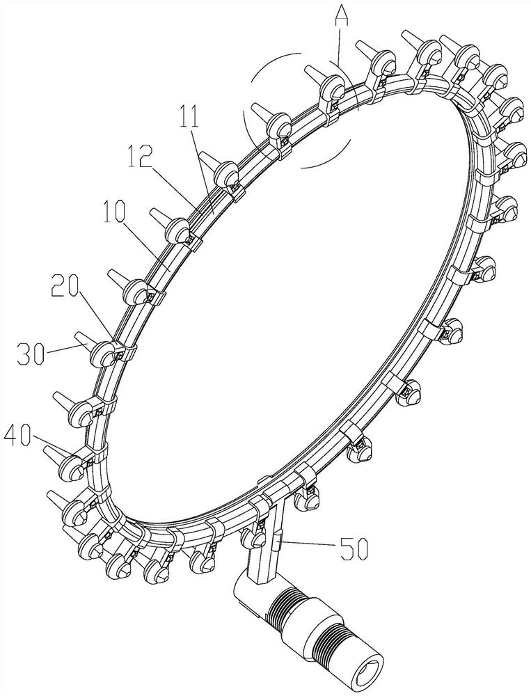
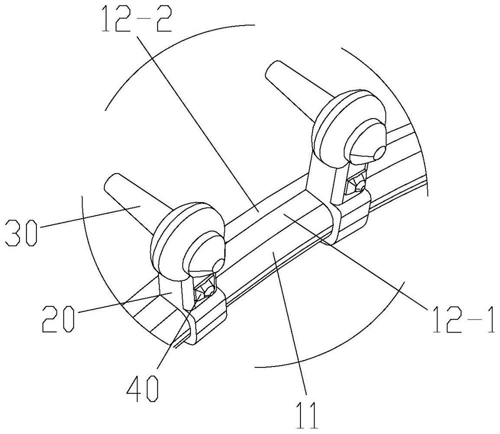
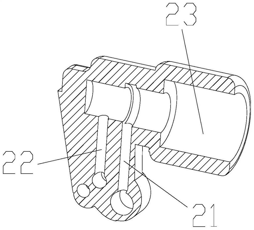
The invention discloses an intelligent fuel oil supply device for an aviation turbine engine, which comprises an oil supply ring and a fuel oil nozzle spraying connecting part, and the oil supply ring comprises a main oil supply ring and at least one auxiliary oil supply ring; one end of the fuel nozzle connecting part is connected with the fuel supply ring, the other end of the fuel nozzle connecting part is connected with the fuel nozzle, a main fuel supply channel, an auxiliary fuel supply channel and a nozzle mounting channel are formed in the fuel nozzle connecting part, and the main fuel supply channel and the auxiliary fuel supply channel are both communicated with the nozzle mounting channel; the fuel oil nozzle is installed on an outlet of the nozzle installation channel, an oil inlet of the fuel oil nozzle is communicated with the main oil supply channel and the auxiliary oil supply channel at the same time through the nozzle installation channel, the main oil supply channel is communicated with the main oil supply ring, and the auxiliary oil supply channel is communicated with the auxiliary oil supply ring. According to the invention, the adjustment range of the oil supply amount is expanded, and the oil supply uniformity of the main-stage fuel nozzle in the circumferential direction of the head of the combustion chamber is realized.

Description

technical field [0001] The invention relates to the field of gas turbine engines, in particular to an intelligent fuel supply device for aviation turbine engines. Background technique [0002] With the rapid development of aero-engines, higher requirements are put forward for various performances. For the combustion chamber in the aircraft turbine engine, it is necessary to ensure a stable combustion state under various operating conditions. [0003] An intelligent control system for controlling the fuel injection mode of the main stage nozzle of the combustion chamber according to the total inlet pressure of the combustion chamber and its working method disclosed in the Chinese invention patent application document with the application number of 202010317491.8, through nozzle grouping and intelligent control The opening and closing of multiple oil circuits solves the disadvantages of poor atomization, low combustion efficiency, and fuel coking and carbon deposition caused ...

Claims


Application Information

Patent Timeline
IPC IPC(8): F02C7/22F02C7/232F02C9/26
CPCF02C7/22F02C7/232F02C9/26Y02T50/60
Inventor 于锦禄徐哲霖焦城阳张旭赵兵兵尉洋张磊程伟达
Owner AIR FORCE UNIV PLA
Learn More