Special-shaped concrete structure formwork installation and construction method
A concrete structure and construction method technology, applied in the direction of formwork/formwork/work frame, connectors of formwork/formwork/work frame, building structure, etc., can solve the problem of low installation quality, complicated process, and inconvenient adjustment and other issues to achieve the effect of improving construction quality, speeding up project progress, and improving processing and construction efficiency
- Summary
- Abstract
- Description
- Claims
- Application Information
AI Technical Summary
Problems solved by technology
Method used
Image
Examples
Embodiment 1
[0041] The embodiment of the present invention discloses a method for installing and constructing a formwork for a special-shaped concrete structure, comprising the following construction steps:
[0042] Step 1: According to the design drawings, establish a steel structure model, conduct collision analysis on the steel structure model, and export the size data and position labels of the steel structure model;
[0043] Step 2: The construction site is positioned and laid out, the horizontal control line is drawn on the construction ground, and the position of the horizontal keel is determined by the spirit level;
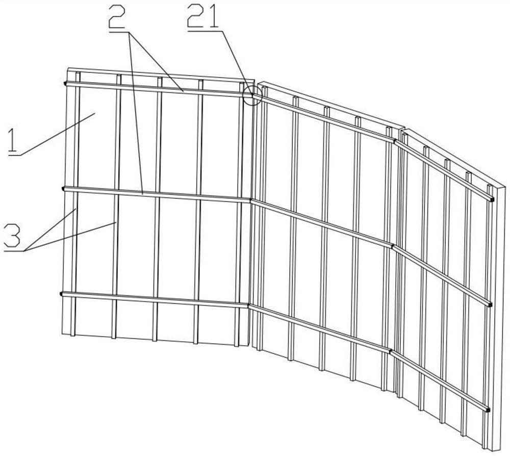
[0044] Step 3: Binding the steel bars according to the positions marked by the positioning and lay-out lines, when the steel bars are bound, a multi-faceted steel mesh is formed by tying the steel bars in the form of broken lines, and the panels 1 are installed on both sides of the steel mesh in turn;
[0045] Step 4: Install the back corrugation on the installed pan...
Embodiment 2
[0047] On the basis of Example 1, increase:
[0048] In step 1, the reinforcement structure model is subjected to collision analysis, including structural collision analysis when the installation is completed and collision analysis during the installation process. The collision analysis during the installation process is realized by simulating the installation process with BIM software.
[0049] In step 2, the position of the main keel 2 is determined by the level meter, and the level meter determines the position of a main keel 2 by testing two points.
[0050] In step 3, the panels 1 are sequentially installed on both sides of the steel mesh, and at the same time, the panels 1 on both sides are connected and fixed by means of tension bolts.
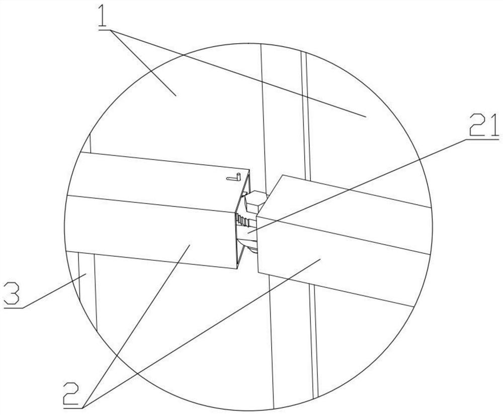
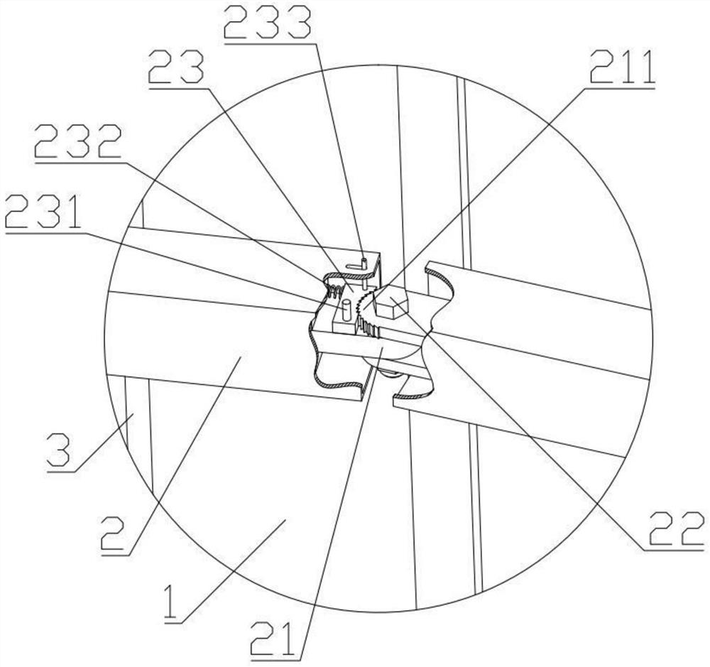
[0051] When installing the main keel 2 in step 4, first connect the adjacent main keel 2 with the hinge 21, and then install the main keel 2 on the panel 1 as a whole. Fit, and then use the self-locking block 23 and the hinge bolt 22 to ...
Embodiment 3
[0053] On the basis of Example 2, increase:
[0054] In step 3, the HVAC pipes and the water pipes are reserved and buried during the steel bar binding process.
[0055] After the installation of the panel 1 is completed, the position and angle of the panel 1 are compounded by a level and an inclinometer, and leveled by an electronic automatic leveler.
[0056] One end of the locking block 23 is mounted on one end of the hinge 21 by the locking shaft 231 , and the other end of the locking block 23 controls the locking block 23 to rotate around the locking shaft 231 through the toggle lever 233 . 23 is pushed by the locking spring 232 and realizes the locking function by engaging with the toothed plate 211 .
[0057] After the installation of the main keel 1 is completed, the position and level of the main keel 1 are compounded, and the angle of the main keel 1 is adjusted by the toggle lever 233 .
PUM
 Abstract
Description
Claims
Application Information
 - R&D
- Intellectual Property
- Life Sciences
- Materials
- Tech Scout
- Unparalleled Data Quality
- Higher Quality Content
- 60% Fewer Hallucinations
Browse by: Latest US Patents, China's latest patents, Technical Efficacy Thesaurus, Application Domain, Technology Topic, Popular Technical Reports.
© 2025 PatSnap. All rights reserved.Legal|Privacy policy|Modern Slavery Act Transparency Statement|Sitemap|About US| Contact US: help@patsnap.com


