Highway pavement joint cutting device with automatic adjusting function for monitoring line installation

A technology of automatic adjustment and angle adjustment device, applied in the direction of road, road, road repair, etc., can solve the problems of frequent adjustment, poor control of adjustment height, different depths of embedded joints, etc., to achieve the effect of easy and rapid adjustment

Pending Publication Date: 2022-06-03
中铁二十局集团第二工程有限公司 +1
View PDF1 Cites 0 Cited by
  • Summary
  • Abstract
  • Description
  • Claims
  • Application Information

AI Technical Summary

Problems solved by technology

[0002] At present, the coverage of monitoring equipment for road safety is becoming more and more extensive, but the monitoring line needs to be hidden under the road surface, so we have a road surface cutting device for monitoring line installation, which can be used to monitor the road for monitoring lines. Corresponding slitting treatment, such as a highway pavement slitting equipment disclosed in CN202010543310.3 for monitoring line installation; but the aforementioned equipment has the following problems during use: 1. It is difficult to pass through the cutting blade in the equipment Cut out cable pre-embedded seams of different widths. Since the number of monitoring devices in different road sections is different, the corresponding embedded cables will also change accordingly, and the depth and width of the pre-embedded seams will also change accordingly; 2. The equipment The cutting saw blade is fixedly installed on the vehicle body through the cutting frame. It cannot make corresponding self-adjustment of the cutting depth according to the different road surface undulations. It needs to be manually adjusted through the vertical lifting mechanism. When the road conditions are complex, not only the adjustment is frequent, but also the adjustment height is not good. Controlled, resulting in different depths of embedded seams cut out;

Method used


Image

  • Highway pavement joint cutting device with automatic adjusting function for monitoring line installation
  • Highway pavement joint cutting device with automatic adjusting function for monitoring line installation
  • Highway pavement joint cutting device with automatic adjusting function for monitoring line installation

Examples


Embodiment Construction

[0037] In order to further understand the features, technical means, and specific goals and functions of the present invention, the present invention will be described in further detail below with reference to the accompanying drawings and specific embodiments.

[0038] like Figure 1 to Figure 9 As shown, this application provides:

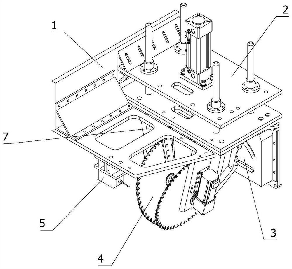
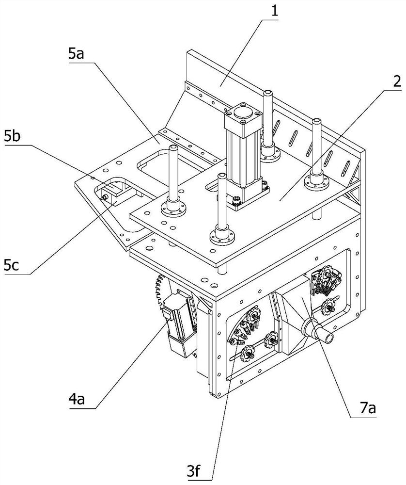
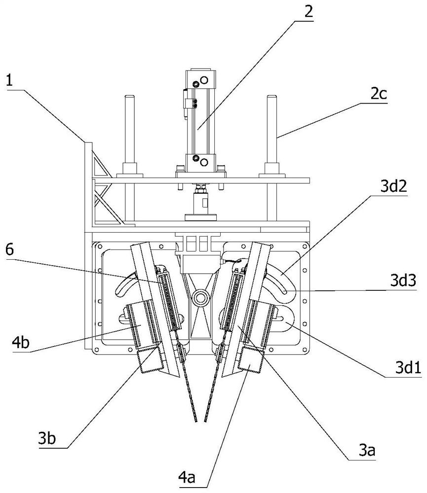
[0039]A road surface slitting device with automatic adjustment function monitoring line installation, comprising a frame 1, a longitudinal attitude adjustment device 2, an angle adjustment device 3, a first angle adjustment mechanism 3a, a second angle adjustment mechanism 3b, and a slitting device 4. The distance detection unit 5, the cooling unit 6 and the cleaning unit 7; the longitudinal attitude adjustment device 2 is fixedly installed on the frame 1 in a vertical state, and the angle adjustment device 3 is vertically fixed and installed on the output end of the longitudinal attitude adjustment device 2, so The angle adjustment device 3 is ...


PUM


Abstract

The invention relates to the technical field of municipal engineering equipment, in particular to a highway pavement joint cutting device with an automatic adjusting function for monitoring line installation, which comprises a longitudinal posture adjusting device fixedly installed on a rack in a vertical state, and an angle adjusting device vertically and fixedly installed at the output end of the longitudinal posture adjusting device. The angle adjusting device is composed of a first angle adjusting mechanism and a second angle adjusting mechanism. A first joint cutting mechanism and a second joint cutting mechanism are fixedly mounted at the output ends of the first angle adjusting mechanism and the second angle adjusting mechanism respectively; the distance detection unit is fixedly mounted on the rack in a horizontal state; the cooling unit is detachably and fixedly mounted on the angle adjusting device; the cleaning unit is detachably mounted on one side of the cooling unit; the depth and the width of the pre-buried pit can be automatically changed according to the specification of the monitoring cable, self-adaption can be carried out according to the road condition of the cut joint, and it is ensured that the depth and the size of the cut pre-buried pit in the road surface are consistent.

Description

technical field [0001] The invention relates to the technical field of municipal engineering equipment, in particular to a road pavement slitting device with automatic adjustment function for monitoring circuit installation. Background technique [0002] At present, the coverage of highway safety monitoring equipment is becoming more and more extensive, but the monitoring line needs to be hidden under the road surface of the highway, so our road surface cutting equipment for monitoring line installation can be used to monitor the road for the monitoring line. Corresponding slitting treatment, such as a road surface slitting equipment for monitoring line installation disclosed by application number CN202010543310.3; but the aforementioned equipment has the following problems during use: 1. It is difficult to pass the cutting blade in the equipment. When cutting out cable pre-embedded seams of different widths, due to the different number of monitoring devices in different sec...

Claims


Application Information

Patent Timeline
Patent Type & Authority Applications(China)
IPC IPC(8): E01C23/09
CPCE01C23/0933
Inventor 何武王静梅王平玉赵明雄张志斌屈鹏罗世军
Owner 中铁二十局集团第二工程有限公司
Why Eureka
Try Eureka