
Energy-saving buffer device for new energy automobile

A technology of new energy vehicles and buffer devices, applied in electric vehicles, power management, vehicle components, etc., can solve problems such as large inertia, spindle wear, energy waste of vehicle sliding, etc., to reduce resonance, avoid wear, and save energy. Effect

Active Publication Date: 2022-06-03
深圳弘富源科技有限公司
View PDF24 Cites 0 Cited by
  • Summary
  • Abstract
  • Description
  • Claims
  • Application Information

AI Technical Summary

Problems solved by technology

[0004] Based on this, it is necessary to address the above problems and propose an energy-saving buffer device for new energy vehicles that can effectively recover the sliding energy of the vehicle, reduce wear and tear during braking, achieve deceleration, and reduce the inertia of the vehicle during braking. , in order to solve the problems that the prior art proposed in the above-mentioned background technology will cause waste of energy when the vehicle slides, cause greater wear to the main shaft during braking, and cause greater inertia during braking

Method used


Image

  • Energy-saving buffer device for new energy automobile
  • Energy-saving buffer device for new energy automobile
  • Energy-saving buffer device for new energy automobile

Examples


Embodiment 1

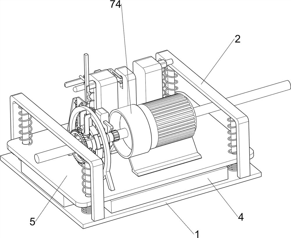
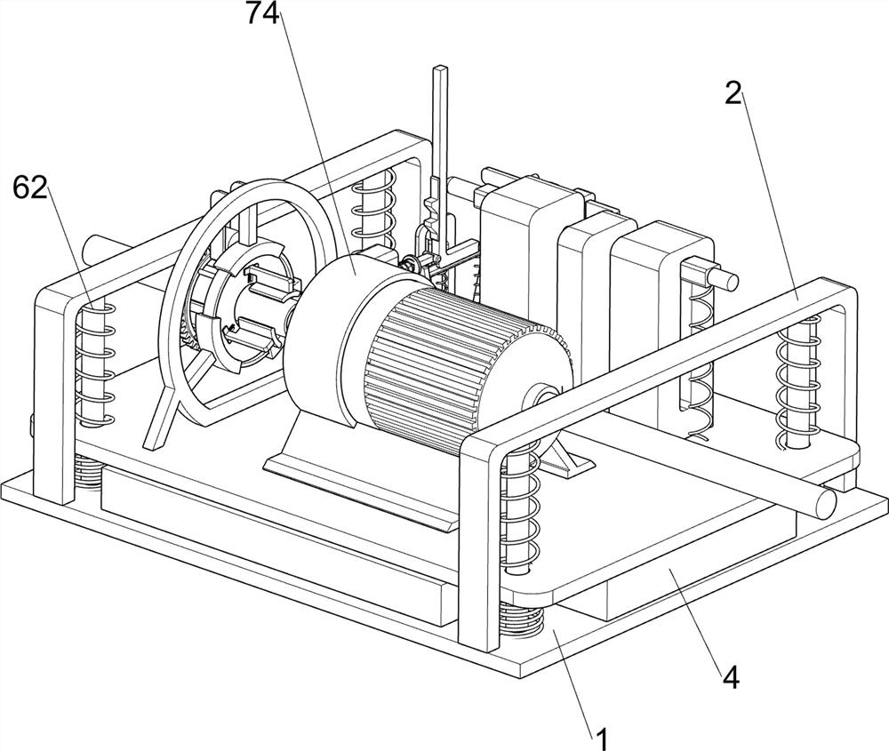
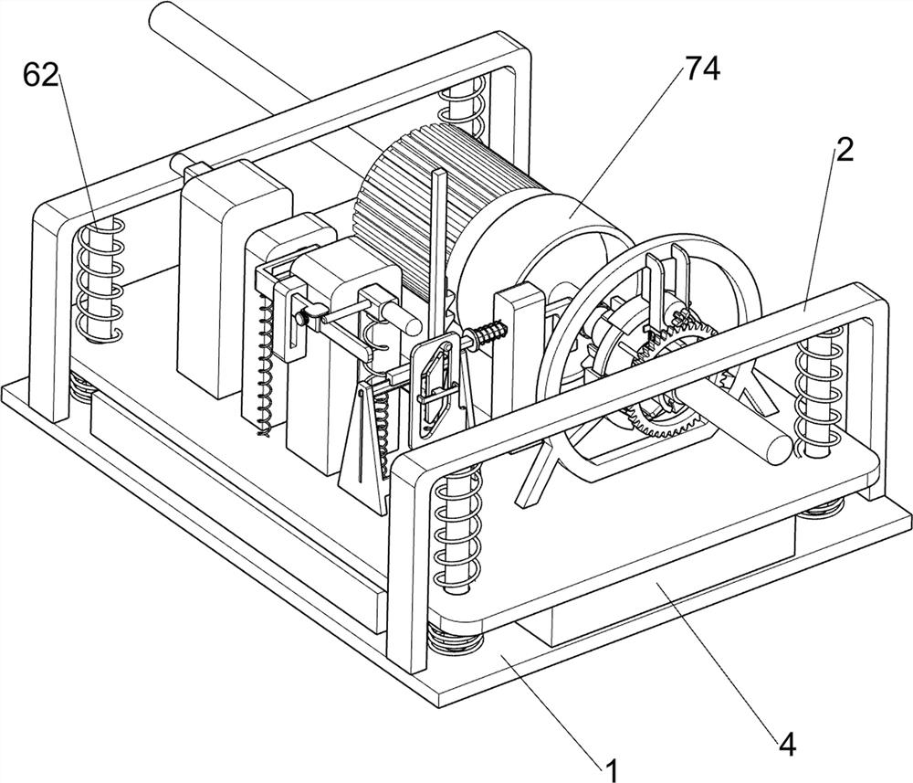
An energy-saving buffer device for new energy vehicles, such as figure 1 , figure 2 , image 3 , Figure 4 , Figure 5 , Image 6 , Figure 7 , Figure 8 , Figure 9 , Figure 10 and Figure 11 As shown, it includes a base plate 1, a U-shaped frame 2, a fixed guide rod 3, a shock pad 4, a mounting groove plate 5, a resonance mitigation component 6, an energy recovery component 7, an electromagnet control component 8 and a lock buffer component 9, A U-shaped frame 2 is symmetrically fixed on the top of the bottom plate 1, and a pair of fixed guide rods 3 are fixed together between the U-shaped frame 2 and the bottom plate 1. A shock-absorbing pad 4 is placed on the top of the bottom plate 1, and the shock-absorbing pad 4 is used for shock absorption and buffering. , the four fixed guide rods 3 are jointly slidably connected with an installation groove plate 5, the installation groove plate 5 is located above the shock-absorbing pad 4, and a resonance mitigation component...

Embodiment 2

On the basis of Example 1, as Figure 12 and Figure 13 As shown, the spot brake buffer assembly 10 is also included. The spot brake buffer assembly 10 is arranged on the installation groove plate 5. The spot brake buffer assembly 10 is used to reduce the inertia of the forward tilt of the vehicle during braking. The spot brake buffer assembly 10 includes a fixed groove. Block 101, point brake lever 102, compression spring 103, triangular fixed plate 104, fixed guide groove plate 105, lift slide plate 106, support spring 107, L-shaped rod 108 and dial block 109, the top of the installation groove plate 5 is fixed with a fixed Slot block 101, the upper part of the fixed slot block 101 is slidably connected to the spot brake lever 102, the spot brake lever 102 is used for spot brake, and a compression spring 103 is connected between the spot brake lever 102 and the fixed slot block 101, and the top of the slot plate 5 is installed to be fixed. A triangular fixing plate 104 is co...

Embodiment 3

On the basis of Example 2, as Figure 14 As shown, it also includes a fixed groove ring 11, the main shaft 75 is provided with a fixed groove ring 11, the fixed groove ring 11 is used to reduce the wear of the main shaft 75 when the brake is applied, and the fixed groove ring 11 is located on the right side of the electromagnetic ring 811.

[0046] During the spot braking process, the grooved ring 11 is fixed, and grooves are formed on the fixing groove ring 11 to increase the friction force during spot braking, which is convenient for spot braking, and at the same time can reduce the wear of the main shaft 75 during spot braking.


PUM


Abstract

The invention relates to the field of new energy automobiles, in particular to an energy-saving buffer device for a new energy automobile, which comprises a bottom plate, a U-shaped frame, a fixed guide rod, a shock pad and the like, u-shaped frames are symmetrically and fixedly connected to the top of the bottom plate, a pair of fixed guide rods are jointly and fixedly connected between the U-shaped frames and the bottom plate, and a shock pad is placed on the top of the bottom plate. When the new energy automobile slides due to inertia, the permanent magnet synchronous motor can recover the sliding energy of the automobile, and if the speed is reduced during sliding, the pinion can drive the generator to generate electricity, so that the sliding energy of the automobile can be effectively recovered, the energy is saved, and the purpose of recovering the energy of the automobile due to inertia sliding is achieved.

Description

technical field [0001] The invention relates to the field of new energy vehicles, in particular to an energy-saving buffer device for new energy vehicles. Background technique [0002] Today, when energy problems and environmental pollution problems are intensifying, the development of new energy vehicles has become an important strategy to implement the national requirements for energy conservation and emission reduction, and the development of a low-carbon economy. New energy vehicles refer to the use of unconventional vehicle fuels as power sources, which have the characteristics of energy saving and emission reduction in the process of use. With the development and utilization of new energy, new energy vehicles have gradually become popular. [0003] In the process of driving, new energy vehicles need to be braked frequently. In the existing technology, mechanical resistance is usually used to make the wheels stand still, so as to realize braking. The existing technology...

Claims


Application Information

Patent Timeline
Patent Type & Authority Applications(China)
IPC IPC(8): B60L7/10B60T1/06
CPCB60L7/10B60T1/062Y02T10/72
Inventor 陈鹏
Owner 深圳弘富源科技有限公司
Learn More