
Waste material taking-out mechanical arm of back-end punching machine of injection molding machine

A stamping machine and injection molding machine technology, applied in the field of manipulators, can solve the problems of not being suitable for multi-tasking requirements, and the single function of the automatic retrieving manipulator, so as to achieve the effects of reducing invalid waiting time, limited range of motion, and reducing the injection molding cycle

Active Publication Date: 2022-06-03
NINGBO BEILONG PRECISION MOLDING
View PDF7 Cites 0 Cited by
  • Summary
  • Abstract
  • Description
  • Claims
  • Application Information

AI Technical Summary

Problems solved by technology

However, the function of the automatic retrieving manipulator in this utility model is relatively single, and it is limited to retrieving materials from the injection molding machine, which is not suitable for the multi-task requirements of the online operation of the injection molding machine and the stamping machine.

Method used


Image

  • Waste material taking-out mechanical arm of back-end punching machine of injection molding machine
  • Waste material taking-out mechanical arm of back-end punching machine of injection molding machine
  • Waste material taking-out mechanical arm of back-end punching machine of injection molding machine

Examples


Embodiment 1

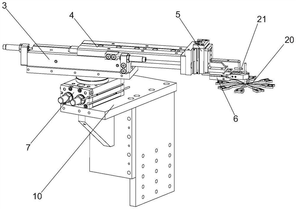
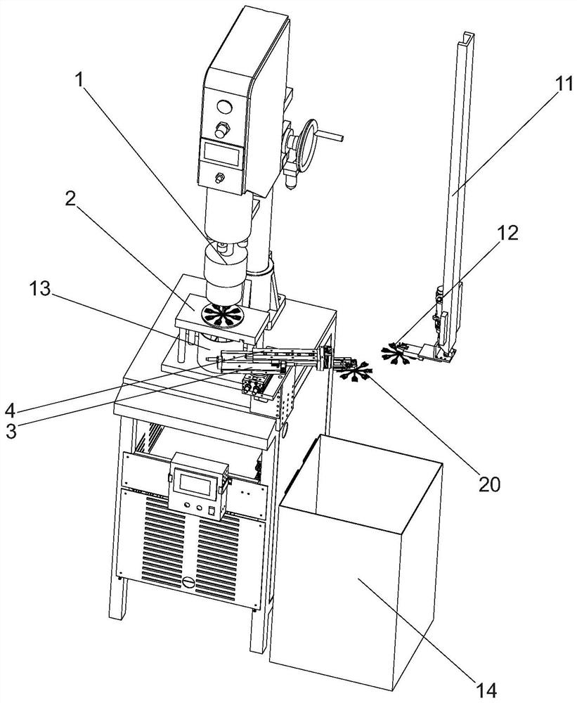
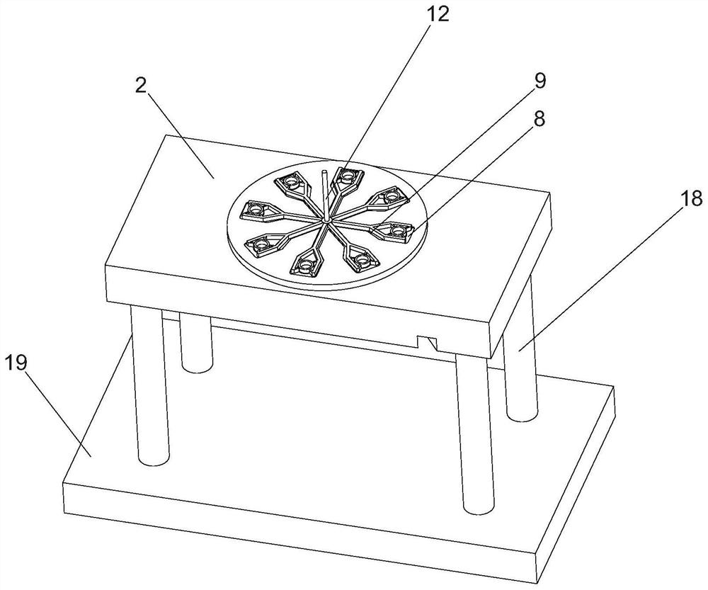
like Figure 1 to Figure 3 As shown, a waste removal manipulator of a punching machine at the back end of an injection molding machine is arranged next to a punching jig 2 of the punching machine, and the punching jig 2 is located directly under the punch 1 of the punching machine, and passes through four jigs. The support rod 18 is overhead fixed on the jig supporting base plate 19, and the jig supporting base plate 19 is fixed on the working table surface of the punching machine through bolts. A material receiving box 13 is placed on the top surface of the jig supporting bottom plate 19 , and the material receiving box 13 is located directly below the punching fixture 2 and is used for receiving the blanking material produced by the punch 1 punching. The punching machine is located downstream of an injection molding machine, and an injection molding machine reclaimer 11 is arranged between the punching machine and the injection molding machine. The product 12 is in the shape...

Embodiment 2

Embodiment 3

There are two stamping jigs 2, all of which are located on a jig rotation turntable. The jig rotation turntable includes a rotary arm 15, a lifting table 16 and a transposition motor 17. The output end of the transposition motor 17 is connected to the center key of the rotary arm 15. connected, the two punching fixtures 2 are respectively fixed on both ends of the rotating arm 15 . The lifting table 16 includes a jib lifting cylinder and a supporting plate. The jib lifting cylinder is fixed on the working surface of the punching machine, the supporting plate is fixed on the piston rod of the jib lifting cylinder, and two jib lifting cylinders are slidably connected to the jib lifting cylinder. The guide rod is parallel to the piston rod of the jib lift cylinder and connected to the bottom of the pallet. A motor suspension 22 is fixed on the top of the support plate, and the transposition motor 17 is fixed under the top plate of the motor suspension 22 . The transposition motor...


PUM


Abstract

The invention discloses a waste taking-out manipulator of a punching machine at the back of an injection molding machine, the waste taking-out manipulator of the punching machine is arranged beside a punching jig of the punching machine, the waste taking-out manipulator of the punching machine comprises a material pulling mechanism and a translation mechanism, the material pulling mechanism is located on the translation mechanism, and the material pulling mechanism is used for pulling out punched waste from the punching jig. And the translation mechanism is used for conveying the punched waste away from the punching jig. The rear half section of the injection molding machine taking manipulator in the prior art can be replaced, the invalid waiting time of the injection molding machine taking manipulator is shortened, and therefore the whole injection molding period is shortened. Workload of the injection molding machine taking manipulator can be shared, movement of the injection molding machine taking manipulator can be simplified, abrasion of the injection molding machine taking manipulator is reduced, and the service life of the injection molding machine taking manipulator is prolonged.

Description

technical field [0001] The present invention relates to a manipulator, more particularly, to a manipulator for taking out scraps of a punching machine in the back-end of an injection molding machine. Background technique [0002] The competition in the injection molding industry is relatively fierce, and all manufacturers try their best to reduce costs and increase production capacity with the utmost efforts to tap the potential in order to improve their competitiveness. Injection cycle is one of the most important parameters for cost control and capacity control. Injection molding machine + reclaiming manipulator is the most common front-end configuration in the field of injection molding at present. For products that need to be stamped after being ejected, manufacturers often combine the injection molding machine and the stamping machine into a line, and the reclaiming manipulator is given the function of connecting the past and the future, which needs to be completed. If...

Claims


Application Information

Patent Timeline
Patent Type & Authority Applications(China)
IPC IPC(8): B29C43/34B29C43/50B29C43/58B29C45/00B29C45/17
CPCB29C45/17B29C45/0055B29C43/34B29C43/58B29C43/50B29C2045/1784B29C2043/3411B29C2043/5069Y02W30/62
Inventor 张世泷李振锋罗忠惠闫伟
Owner NINGBO BEILONG PRECISION MOLDING
Learn More