
Spiral grating groove loaded circular waveguide TM01-TE01 mode converter

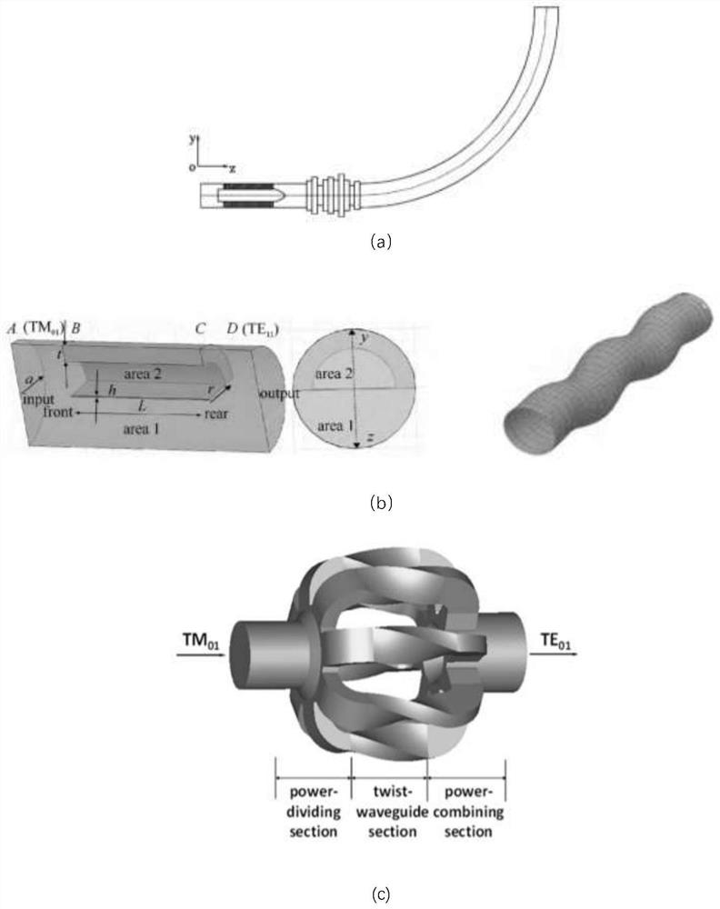
A mode converter and circular waveguide technology, applied in waveguide devices, circuits, electrical components, etc., can solve the problems of large mode converter size, increased difficulty in process realization, complex structure, etc., and achieve high polarization conversion efficiency, The effect of small size and high transmission efficiency

Active Publication Date: 2022-05-31
UNIV OF ELECTRONICS SCI & TECH OF CHINA
View PDF3 Cites 0 Cited by
  • Summary
  • Abstract
  • Description
  • Claims
  • Application Information

AI Technical Summary

Problems solved by technology

[0005] The design idea of ​​the above schemes is to introduce the intermediate transition mode and realize the mode conversion by multi-level conversion and segmentation, which will lead to a large size and complex structure of the mode converter, which will significantly increase the difficulty of process realization.

Method used


Image

  • Spiral grating groove loaded circular waveguide TM01-TE01 mode converter
  • Spiral grating groove loaded circular waveguide TM01-TE01 mode converter
  • Spiral grating groove loaded circular waveguide TM01-TE01 mode converter

Examples


Embodiment Construction

[0029] The technical solution of the present invention will be further described below in conjunction with the embodiments and the accompanying drawings.

[0030] Circular waveguideTM loaded with spiral grating grooves centered at 12GHz 01 -TE 01 Mode converters for example, such as Figure 5 As shown, the mode converter includes a coaxial and sequentially connected input circular waveguide, an input transition section, a mode conversion section, an output transition section, and an output circular waveguide; the input transition section and the output transition section are horn shapes with a linear gradient in radius; the mode The transformation section is a circular waveguide with equidistant spiral grating grooves on the inner wall, and the equidistant spiral grating grooves are composed of several spiral grooves arranged periodically; the circular waveguideTM 01 The beam is fed from the input circular waveguide, and finally output from the output circular waveguide to r...


PUM


Abstract

The invention discloses a spiral grating groove loaded circular waveguide TM01-TE01 mode converter, and belongs to the technical field of microwave waveguides. The converter comprises an input circular waveguide, an input transition section, a mode conversion section, an output transition section and an output circular waveguide which are coaxial and sequentially connected, the input transition section and the output transition section are in a horn shape of which the radius is linearly gradually changed; the mode conversion section is a circular waveguide of which the inner wall is provided with equidistant spiral grating grooves; and the equidistant spiral grating grooves are formed by periodically arranging a plurality of spiral grooves. The reflection grating theory and the waveguide mode transmission theory are combined, the spiral grating groove is loaded on the inner wall of the circular waveguide, the mode converter has the advantages of being high in transmission efficiency, compact in structure, small in size and the like, and the problems that an existing mode converter is large in size, large in machining difficulty and the like are solved.

Description

technical field [0001] The invention belongs to the field of microwave waveguide technology, in particular to a circular waveguideTM with small size, high conversion rate and compact spiral grating groove loading 01 -TE 01 mode converter. Background technique [0002] With the development of high-power microwave technology, the demand for devices operating in different waveforms or modes is also increasing. When considering the construction of the overall system, the connection and transmission of different devices are more important, so the mode conversion has become an important part of it. [0003] Circular waveguide TE 01 Mode is suitable for long-distance transmission of millimeter waves due to its advantages of relatively few competing modes and low transmission loss at high frequencies. However TE 01 The mode is difficult to generate directly, and the output mode of the general high-power microwave source and oscillator is a circular waveguide TM 01 mode, so it ...

Claims


Application Information

Patent Timeline
Patent Type & Authority Applications(China)
IPC IPC(8): H01P1/163
CPCH01P1/163
Inventor 李浩刘洁淼刘思迪
Owner UNIV OF ELECTRONICS SCI & TECH OF CHINA
Learn More