
Array calibration method based on time delay redundancy measurement

A calibration method and time-delay technology, which are applied in measuring devices, devices with phase adjustment/time lag error compensation, orientators for measuring directions, etc., can solve problems such as calibration deviations, achieve high precision, and improve formation Effects of Calibration Accuracy and Stability

Active Publication Date: 2022-05-31
INST OF ACOUSTICS CHINESE ACAD OF SCI
View PDF2 Cites 1 Cited by
  • Summary
  • Abstract
  • Description
  • Claims
  • Application Information

AI Technical Summary

Problems solved by technology

The existing array calibration methods can be roughly divided into two categories: one is passive calibration, which can be realized by using noise sources without the need for additional calibration sound sources, but the inverted array only knows the relative shape, and the initial calibration needs to be based on other information. As a result, operations such as translation, rotation, and flipping can be performed to obtain the true position of each array element; the other type is active calibration, which uses the calibration sound source and combines the GPS position information of the sound source and the reference array element to measure each adjacent array element The real position of each array element relative to the reference array element can be obtained; however, due to the longitudinal correlation oscillation phenomenon in the shallow sea channel, the random fluctuation of the channel, and the influence of environmental noise in the ocean, especially in the calibration signal-to-noise ratio When is low, the traditional method will cause the deviation of the calibration formation due to the accumulation of time delay estimation errors

Method used


Image

  • Array calibration method based on time delay redundancy measurement
  • Array calibration method based on time delay redundancy measurement
  • Array calibration method based on time delay redundancy measurement

Examples


Embodiment 1

[0073] Embodiments of the present invention propose a formation calibration method based on delay redundancy measurement. The steps to implement are as follows:

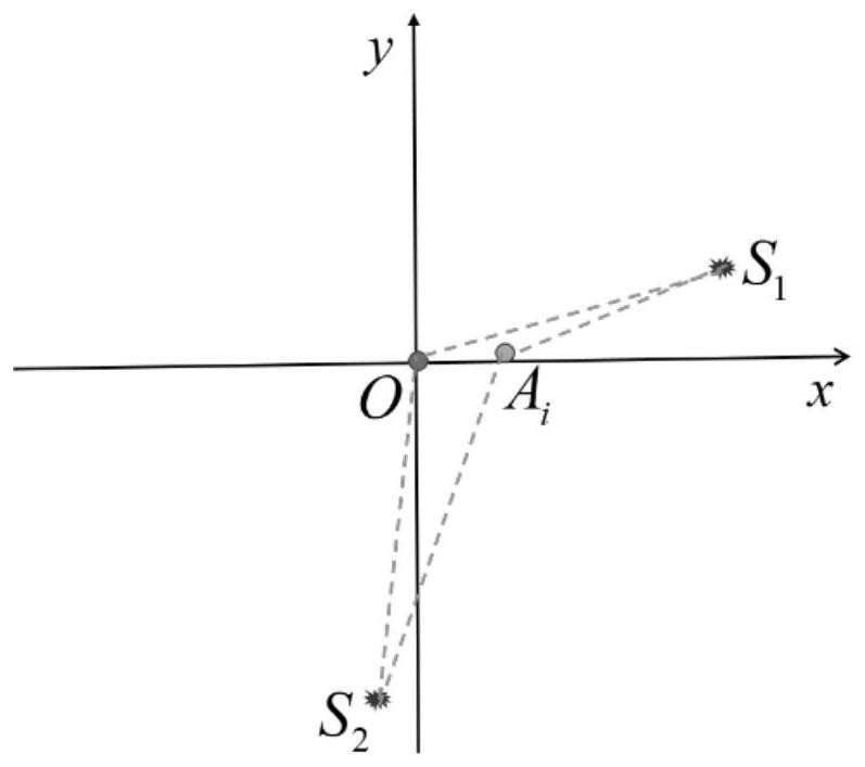
[0074] 1. Arrange two auxiliary sound sources with approximately vertical signal arrival directions at an appropriate distance from the array to emit signals. Record sound source S 1 (X 1 ,Y 1 ), S 2 (X 2 ,Y 2 ) and reference array element O(x 1 ,y 1 ) position coordinates;

[0075] 2. Perform band-pass filter processing on the received signals of all channels of the array to be calibrated;

[0076] 3. Signal-dependent time delay for all I(I-1) / 2 groups of pairwise element combinations carry out estimates,

[0077]

[0078] 4. According to the signal delay vector B of the combination of two array elements, calculate the delay vector P for establishing the relative reference array element: P=Q + B

[0079] in,

[0080]

[0081] The superscript + means to take the pseudo-inverse of the matrix;

...


PUM


Abstract

The invention discloses an array calibration method based on time delay redundancy measurement, and the method comprises the steps: 1), carrying out the steps 2)-3) in sequence for a first auxiliary sound source S1 and a second auxiliary sound source S2: carrying out the band-pass filtering of a signal of one auxiliary sound source received by all array elements of a to-be-calibrated array A; 3) carrying out related time delay estimation on the combined signals of the two array elements of the array A to be calibrated after band-pass filtering processing to obtain a time delay vector relative to a reference array element; 4) establishing a position inversion objective function of each array element of the to-be-calibrated array A according to time delay vectors obtained for the first auxiliary sound source S1 and the second auxiliary sound source S2; and step 5) obtaining the coordinate of each array element through optimization search, thereby completing the calibration of the array A. According to the method, the array element space information is fully utilized, the array calibration precision and stability are improved, and the accuracy of the obtained sound source azimuth angle is higher when the method is adopted to calibrate the array detection target of the array.

Description

technical field [0001] The invention belongs to the technical fields of sonar signal processing and array signal processing, and in particular relates to an array calibration method based on time delay redundancy measurement. Background technique [0002] The formation calibration accuracy has a significant impact on the direction finding performance of the target. The flexible horizontal array deployed on the seabed is often affected by factors such as deployment, internal waves, and surges. The actual formation is often quite different from the preset formation. . Performing array shape calibration can improve the performance of subsequent signal processing algorithms, especially the performance of various adaptive algorithms. The existing array calibration methods can be roughly divided into two categories: one is passive calibration, which can be realized by using noise sources without the need for additional calibration sound sources, but the inverted array only knows ...

Claims


Application Information

Patent Timeline
Patent Type & Authority Applications(China)
IPC IPC(8): G01S7/539G01S3/781G01S3/82
CPCG01S7/539G01S3/781G01S3/82Y02A90/10
Inventor 何琪宫在晓李风华郭良浩
Owner INST OF ACOUSTICS CHINESE ACAD OF SCI
Learn More