
Pipeline two-dimensional flow field flow velocity measurement system and method based on laser Doppler velocity measurement

A technology of Doppler velocity measurement and two-dimensional flow field, which is applied in the directions of full-field flow measurement, velocity/acceleration/impact measurement, fluid velocity measurement, etc. Point flow velocity measurement is inconvenient and other problems, to avoid complex correction problems, multi-point measurement is convenient, and the structure is simple

Pending Publication Date: 2022-05-31
NAT UNIV OF DEFENSE TECH
View PDF0 Cites 0 Cited by
  • Summary
  • Abstract
  • Description
  • Claims
  • Application Information

AI Technical Summary

Problems solved by technology

These devices mainly have the following two disadvantages: (1) interfere with the flow field, causing the flow field to produce flow velocity distribution distortion, and at the same time increase the average flow velocity of the cross-section where the measuring probe is located; (2) multi-point flow velocity measurement is inconvenient, and the flow velocity distribution in the pipeline is unknown The flow field flow measurement accuracy is low
In order to obtain the flow velocity distribution of the two-dimensional flow field, the laser Doppler velocimeter needs to be installed on the two-dimensional coordinate adjustment frame, and the incident angle of light will bring complicated correction problems

Method used


Image

  • Pipeline two-dimensional flow field flow velocity measurement system and method based on laser Doppler velocity measurement
  • Pipeline two-dimensional flow field flow velocity measurement system and method based on laser Doppler velocity measurement
  • Pipeline two-dimensional flow field flow velocity measurement system and method based on laser Doppler velocity measurement

Examples


Embodiment Construction

[0037] The following will clearly and completely describe the technical solutions in the embodiments of the present invention with reference to the accompanying drawings in the embodiments of the present invention. Obviously, the described embodiments are only part of the embodiments of the present invention, not all of them. Based on the embodiments of the present invention, all other embodiments obtained by persons of ordinary skill in the art without creative efforts fall within the protection scope of the present invention.

[0038] It should be noted that all directional indications (such as up, down, left, right, front, back...) in the embodiments of the present invention are only used to explain the relationship between the components in a certain posture (as shown in the accompanying drawings). Relative positional relationship, movement conditions, etc., if the specific posture changes, the directional indication will also change accordingly.

[0039] In addition, in t...


PUM


Abstract

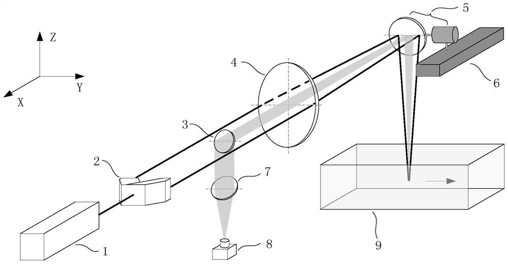
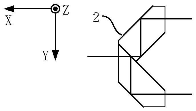
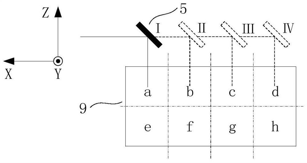
The invention discloses a pipeline two-dimensional flow field flow velocity measurement system and method based on laser Doppler velocity measurement, and the system comprises a laser which is used for outputting a laser beam; the beam splitter is positioned behind the laser and is used for splitting the laser beam into two parallel measuring light beams which are propagated at equal intensity and equal optical path; the focusing reflection assembly is positioned behind the beam splitter and is used for reflecting and converging the two parallel measurement light beams at a flow field to-be-measured point in the pipeline and returning part of scattered light carrying flow field motion information along an original path to form scattered light to be measured; and the detection assembly is located on the light path of the to-be-detected scattered light and is used for collecting the to-be-detected scattered light. The device is applied to the technical field of pipeline flow velocity measurement, interference of a contact type measuring device on a flow field can be avoided, the problem of complex correction caused by a light incident angle when a traditional laser Doppler velocimeter measures two-dimensional flow field flow velocity distribution can also be avoided, the structure is simple, universality is better, and multi-point measurement is convenient.

Description

technical field [0001] The invention relates to the technical field of pipeline flow velocity measurement, in particular to a two-dimensional flow field flow velocity measurement system and method based on laser Doppler velocity measurement. Background technique [0002] Flow measurement is widely used in industrial production, process control, and scientific experiments. Flow parameters have become an important indicator for measuring economic efficiency, production status, environmental supervision, and product performance. With the improvement of production technology and industrial production automation, higher and higher requirements are put forward for the accuracy, reliability, economy and intelligence of flow measurement. [0003] Existing pipeline flow field measuring devices can be divided into contact measuring devices and non-contact measuring devices. Common contact measuring devices, such as differential pressure flow meters, acoustic flow meters, turbine flow...

Claims


Application Information

Patent Timeline
IPC IPC(8): G01P5/26G01P5/00
CPCG01P5/26G01P5/001
Inventor 王琦周健聂晓明王汉睦黄荣陈兰剑席崇宾向志毅
Owner NAT UNIV OF DEFENSE TECH
Learn More