
Gas detection system and method

A gas detection system and the technology of the gas to be measured are applied in the direction of measuring devices, color/spectral characteristic measurement, instruments, etc., and can solve the problems of signal-to-noise ratio reduction, damage to metal films, damage, etc.

Pending Publication Date: 2022-05-31
LASER RES INST OF SHANDONG ACAD OF SCI
View PDF0 Cites 0 Cited by
  • Summary
  • Abstract
  • Description
  • Claims
  • Application Information

AI Technical Summary

Problems solved by technology

The current common quartz-enhanced photoacoustic spectroscopy gas detection technology is a gas contact measurement technology. The quartz tuning fork is embedded in the gas sample to be measured, which limits its application in fields such as long-distance measurement, and if the gas to be measured It is a corrosive gas that will damage the metal film on the surface of the quartz tuning fork, resulting in frequency drift or even damage to the quartz tuning fork
[0003] At present, some scholars have proposed a quartz-enhanced photothermal spectroscopy gas detection technology, which is a non-contact gas detection technology. After the light is absorbed in the gas absorption cell, it is directly incident on the quartz tuning fork arm. On the basis of photothermal effect, the gas is detected, but this method requires direct contact between the laser and the quartz tuning fork, which inevitably produces a lot of thermal noise, because the photothermal signal is proportional to the laser power, but the thermal noise of the quartz tuning fork and the laser The power is exponentially related, so the signal-to-noise ratio of the system will be greatly reduced

Method used


Image

  • Gas detection system and method
  • Gas detection system and method
  • Gas detection system and method

Examples


Embodiment Construction

[0036] Embodiments of the present application are described in detail below, examples of which are shown in the drawings, wherein the same or similar reference numerals denote the same or similar elements or elements having the same or similar functions throughout. The embodiments described below by referring to the figures are exemplary only for explaining the present application, and are not construed as limiting the present application.

[0037] Those skilled in the art will understand that unless otherwise stated, the singular forms "a", "an", "said" and "the" used herein may also include plural forms. It should be further understood that the word "comprising" used in the specification of the present application refers to the presence of the features, integers, steps, operations, elements and / or components, but does not exclude the presence or addition of one or more other features, Integers, steps, operations, elements, components, and / or groups thereof. It will be under...


PUM


Abstract

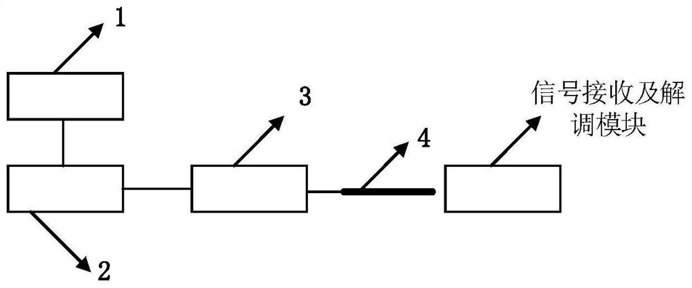
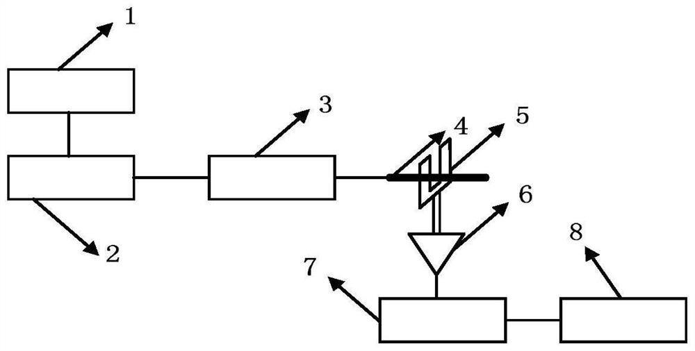
According to the gas detection system and method provided by the invention, the signal receiving module can be prevented from being in direct contact with gas molecules and laser at the same time, the signal receiving module can be protected from being damaged by corrosive gas, and the thermal noise of the system can be reduced, so that the gas detection precision is ensured, and the signal-to-noise ratio of the system is improved. The system comprises a temperature control current source, a laser, a gas absorption cell, a hot wire type optical fiber and a signal receiving and demodulation module, the temperature control current source is connected with the laser device, an output end optical fiber of the laser device is connected with an input end of the gas absorption cell, an output end optical fiber of the gas absorption cell is connected with the hot-wire type optical fiber, the hot-wire type optical fiber is close to the signal receiving and demodulation module, the hot-wire type optical fiber can convert optical energy into heat energy, and the signal receiving and demodulation module is connected with the temperature control current source. And the signal receiving and demodulating module can detect the concentration of the gas to be detected in the gas absorption cell by utilizing the heat energy converted by the hot-wire type optical fiber.

Description

technical field [0001] The present application relates to the field of gas detection, in particular to a gas detection system and method. Background technique [0002] With the progress of society and the development of science and technology, high-precision monitoring of gas concentration is of great significance in many fields such as ensuring oil and gas exploitation, biopharmaceutical safety, air pollution prevention and control, food and drug safety, etc. The current common quartz-enhanced photoacoustic spectroscopy gas detection technology is a gas contact measurement technology. The quartz tuning fork is embedded in the gas sample to be measured, which limits its application in fields such as long-distance measurement, and if the gas to be measured As a corrosive gas, it will damage the metal film on the surface of the quartz tuning fork, resulting in frequency drift or even damage to the quartz tuning fork. [0003] At present, some scholars have proposed a quartz-e...

Claims


Application Information

Patent Timeline
IPC IPC(8): G01N21/17G01N21/31G01N21/39G01N21/01
CPCG01N21/1702G01N21/314G01N21/39G01N21/01G01N2021/3148G01N2021/0112
Inventor 张秦端魏玉宾杜晓萌宫卫华张婷婷王兆伟李艳芳王纪强张伟
Owner LASER RES INST OF SHANDONG ACAD OF SCI
Learn More