Bridge floor cast-in-place concrete guardrail installation reference frame

A technology of installation datum and concrete, which is applied in the direction of bridges, bridge construction, erection/assembly of bridges, etc. It can solve the problems of no automatic level adjustment function, no lifting mobile structure, inconvenient use, etc., and achieve automatic adjustment mode , accurate position, convenient operation and use

Inactive Publication Date: 2022-05-31
马银熠
View PDF0 Cites 0 Cited by
  • Summary
  • Abstract
  • Description
  • Claims
  • Application Information

AI Technical Summary

Problems solved by technology

[0007] The purpose of the present invention is to provide a reference frame for installation of cast-in-place concrete guardrails on bridge decks, which solves the problem of installation of existing cast-in-place concrete guardrails on bridge decks by setting up and down movable structures, lift-type adjustment structures, slide rails and laser line throwing instruments. The reference frame, when installing, needs to move the position of the reference frame after installing a guardrail frame steel bar, and then assists in the installation of the next guardrail frame steel bar, which is not very convenient to use, and does not have automatic level adjustment function, and does not have lift Type mobile structure, not easy to shift the problem

Method used


Image

  • Bridge floor cast-in-place concrete guardrail installation reference frame
  • Bridge floor cast-in-place concrete guardrail installation reference frame
  • Bridge floor cast-in-place concrete guardrail installation reference frame

Examples


Embodiment Construction

[0044] The following will clearly and completely describe the technical solutions in the embodiments of the present invention with reference to the drawings in the embodiments of the present invention.

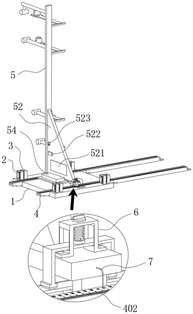
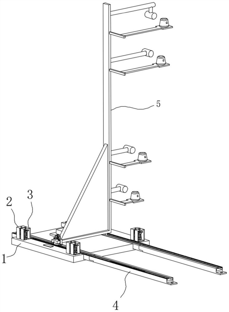
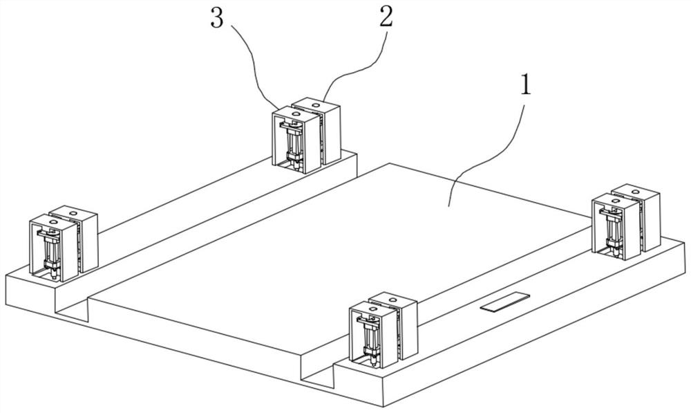
[0045] see Figure 1-4 with Figure 9 As shown, the present invention is a bridge deck cast-in-place concrete guardrail installation reference frame, including a base 1, a lifting type mobile structure 2, a lifting type adjustment structure 3, a slide rail 4, a reference fixing frame 5, a locking structure 6 and an indicator rod 7. A mounting groove 11 is provided on the top surface of the base 1, and a control switch 12 is fixed on one edge of the top surface of the base 1, and two symmetrical mounting holes 101 are provided inside the mounting groove 11;

[0046] The base 1 is detachably connected with a slide rail 4 through screws, the size of the slide rail 4 matches the size of the installation groove 11, one end of the slide rail 4 is the first connector 41, and the oth...


PUM


Abstract

The invention discloses a bridge deck cast-in-place concrete guardrail installation reference frame, and relates to the technical field of bridge deck guardrail construction. The device comprises a base, a lifting type moving structure, a lifting type adjusting structure, a reference fixing frame and a locking structure, the lifting type moving structure and the lifting type adjusting structure are fixed to the four corners of the base, sliding rails are detachably connected to the base through screws, and the reference fixing frame is slidably connected to one set of sliding rails. Through the synchronous action of a group of lifting type adjusting structures and the auxiliary action of each laser demarcation device, the straight line type and the accurate position in the guardrail steel bar binding process are ensured by positioning the plane and the elevation of the skeleton steel bar, the welded top surfaces of the guardrail steel bars are ensured to be the same in height and the side surfaces are ensured to be the same in height by utilizing construction laser assistance, and the construction efficiency is improved. In addition, a lifting type adjusting structure is arranged, the automatic horizontal adjusting function is achieved, the adjusting mode is very automatic, a lifting type moving structure is arranged, and displacement is convenient.

Description

technical field [0001] The invention belongs to the technical field of bridge deck guardrail construction, in particular to a bridge deck cast-in-place concrete guardrail installation reference frame. Background technique [0002] At present, when pouring concrete guardrails on the bridge deck, it is necessary to install welded guardrail skeleton reinforcement first. In this process, in order to achieve the relative position accuracy Generally, the reference frame is used to assist in the positioning of the guardrail frame reinforcement. The existing reference frame still has the following disadvantages in actual use: [0003] 1. The existing bridge deck cast-in-place concrete guardrail is installed with a reference frame. During installation, the position of the reference frame needs to be moved after each installation of a guardrail skeleton reinforcement, and then the installation of the next guardrail skeleton reinforcement is assisted, which is not very convenient to us...

Claims


Application Information

Patent Timeline
IPC IPC(8): E01D21/00E04G21/18
CPCE01D21/00E04G21/18E04G21/1841
Inventor 马银熠王博杨成安叶宁波傅利军宣炳森叶舟迪湛守库徐建国金海斌邵雅红徐银海阮军
Owner 马银熠
Why Eureka
Try Eureka