
Planar Luneberg lens antenna based on thin cloth phased array feed

A technology of Lunberg lens antenna and plane lens, which is applied in the directions of antenna arrays, antennas, and antenna arrays that are energized separately, can solve the problems of restricting the use requirements of ultra-high-gain wireless communication scenarios, reducing the transmission power, and high cost, and achieves the reduction of The effect of antenna profile height, quantity reduction, and processing cost reduction

Active Publication Date: 2022-05-27
UNIV OF ELECTRONICS SCI & TECH OF CHINA
View PDF21 Cites 2 Cited by
  • Summary
  • Abstract
  • Description
  • Claims
  • Application Information

AI Technical Summary

Problems solved by technology

[0006] In the paper "Wide-Angle Scanning Lens at 28 GHz Fed by AntennaArray", Zhishu Qu et al. organically combined a high-gain and low-cost lens antenna with a phased antenna with large-angle fast electrical scanning. Although the scanning capability of ±58° is achieved, However, as the scanning angle of the 3D dielectric lens increases, the number of units excited by the feed array decreases, resulting in a significant decrease in the equivalent isotropic radiated power (EIRP) of the system index, which seriously restricts the use of ultra-high-gain wireless communication scenarios; electronic technology In the "Research on Phased Lens Antenna Technology", the team of Professor Qu Shiwei of the University took EIRP as the optimization goal, and achieved a scanning range of ±15° by using a 4×4 phased array with full power to irradiate the transmission array; however, due to the large number of transmission arrays The layer structure and the full array arrangement of feed sources require 16 TR channels to realize beam scanning, which is expensive

Method used


Image

  • Planar Luneberg lens antenna based on thin cloth phased array feed
  • Planar Luneberg lens antenna based on thin cloth phased array feed
  • Planar Luneberg lens antenna based on thin cloth phased array feed

Examples


Embodiment 1

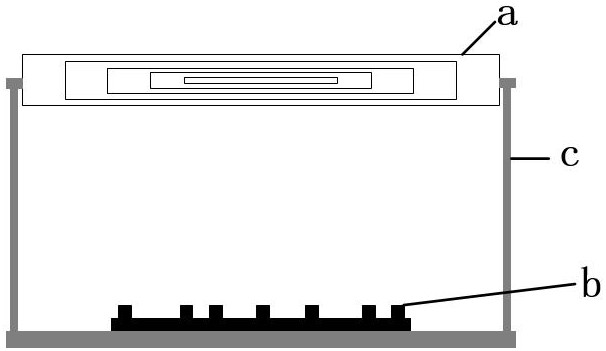
[0049] A planar Lumberg lens antenna based on sparse phased array feeding is designed and obtained according to the following steps:

[0050] Step 1. According to the indicator, the 10 dB beam width of the feed antenna is 34°, and the spherical Lunberg lens antenna is designed through electromagnetic simulation software. Specifically, in this embodiment, a spherical Lunberg lens composed of 5 layers of dielectric materials is first designed. Antenna, the relative permittivity of the innermost dielectric material of the spherical Lunberg lens antenna is 2, and the relative permittivity decreases at equal intervals from the inside to the outside, and the electrical parameter of the outermost material is 1; and the spherical Lunberg lens antenna The radius R;

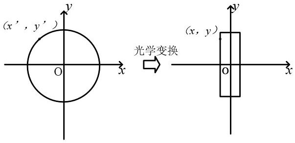
[0051] Step 2. Use optical transformation to compress the spherical Lumberg lens antenna obtained in step 1 into a cylindrical plane lens. The specific process is:

[0052] In the Cartesian coordinate system, the spherica...


PUM


Abstract

The invention aims to provide a planar luneberg lens antenna based on thin cloth phased array feed, and belongs to the technical field of antennas. According to the antenna, a spherical luneberg lens antenna is compressed into a plane structure through optical transformation, and then a large-spacing thin cloth feed array matched with the plane lens structure is optimized by using an optimization algorithm, so that after the sparse layout of the antenna is determined, the excitation amplitude of the antenna at different scanning angles in the working process is not changed, and the antenna stability is improved. The EIRP index in the scanning range is ensured; meanwhile, the antenna also has the advantages of high gain, low profile and low cost, and has relatively high engineering practicability.

Description

technical field [0001] The invention belongs to the technical field of antennas, and in particular relates to a plane Lumberg lens antenna based on sparse phased array feeding. Background technique [0002] With the rapid development of wireless communication technologies such as 5G and low-orbit satellite communication, the application scenarios of wireless communication are becoming more and more complex. As an important device in a wireless communication system, the performance requirements of the antenna are becoming higher and higher. In wireless communication scenarios such as 5G and low-orbit satellite communication, there are practical applications such as long-distance communication, beam alignment, and small space assembly. Therefore, antennas are required to have high gain, fast beam switching, and low profile requirements. [0003] Phased array antennas are the most widely used beam scanning antennas in communication systems. They have the capabilities of fast w...

Claims


Application Information

Patent Timeline
IPC IPC(8): H01Q15/08H01Q19/06H01Q1/12H01Q21/06
CPCH01Q15/08H01Q19/06H01Q1/12H01Q21/061Y02D30/70
Inventor 郑斌程钰间鲁国林
Owner UNIV OF ELECTRONICS SCI & TECH OF CHINA
Learn More