Thermoelectric conversion device, preparation method thereof and thermoelectric conversion system

A technology of thermoelectric conversion devices and electrodes, applied in the manufacture/processing of thermoelectric devices, thermoelectric devices using only Peltier or Seebeck effect, photovoltaic power generation, etc., can solve the problems of low thermoelectric conversion efficiency, thermoelectric conversion devices and system application limitations, etc. , to achieve the effect of increasing thermoelectric conversion efficiency or cooling power, increasing thermal rectification effect, and increasing thermoelectric figure of merit

Pending Publication Date: 2022-05-27
INST OF ENGINEERING THERMOPHYSICS - CHINESE ACAD OF SCI
View PDF0 Cites 0 Cited by
  • Summary
  • Abstract
  • Description
  • Claims
  • Application Information

AI Technical Summary

Problems solved by technology

[0004] At present, the thermoelectric conversion efficiency of thermoelectric conversion devices is generally low (ZT≈1), and the application of thermoelectric conversion devices and systems is greatly limited.

Method used


Image

  • Thermoelectric conversion device, preparation method thereof and thermoelectric conversion system
  • Thermoelectric conversion device, preparation method thereof and thermoelectric conversion system
  • Thermoelectric conversion device, preparation method thereof and thermoelectric conversion system

Examples


Embodiment 1

[0037] see figure 1 , this embodiment provides a thermoelectric conversion device, including:

[0038] the first electrode 2;

[0039] P-type elements 6 and N-type elements 7 located on one side surface of the first electrode 2 and electrically connected to the first electrode 2;

[0040] the second electrodes 3 respectively located on the side of the P-type element 6 and the N-type element 7 away from the first electrode 2;

[0041] the first heat conducting plate 1 located at the first electrode 2 away from the P-type element 6 and the N-type element 7;

[0042] a second heat-conducting plate 4 located at the second electrode 3 away from the P-type element 6 and the N-type element 7;

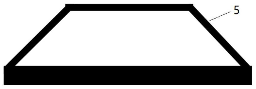
[0043] The microstructure 5 is located on the side surface of the first thermally conductive plate 1 away from the first electrode 2 , and / or is located on a surface of the first thermally conductive plate 1 facing the first electrode 2 . The side surface is in contact with the first electro...

Embodiment 2

[0057] The present invention also provides a preparation method of a thermoelectric conversion device, comprising:

[0058] S1. Provide a first thermally conductive plate 1 and a second thermally conductive plate 4, the first thermally conductive plate 1 has opposite first sides 11 and second sides 12, and the second thermally conductive plate 4 has opposite third sides 41 and The fourth side 42, at least one of the first side 11, the second side 12, the third side 41 and the fourth side 42 is formed with microstructures 5, the microstructures 5 have oppositely disposed first surfaces and a second surface, the area of ​​the first surface is smaller than the area of ​​the second surface;

[0059] S2. Provide a first electrode 2 and a second electrode 3; place a P-type element 6 between the first electrode 2 and part of the second electrode 3, and place an N-type element 7 between the first electrode 2 and another part of the second electrode 3;

[0060] S3. Dispose the first ...

Embodiment 3

[0064] This embodiment provides a thermoelectric conversion system, including the thermoelectric conversion device provided in Embodiment 1. The thermoelectric conversion system has all the advantages of the thermoelectric conversion device, which will not be repeated here.


PUM

PropertyMeasurementUnit
Thicknessaaaaaaaaaa
Thermal conductivityaaaaaaaaaa
Thicknessaaaaaaaaaa

Abstract

The invention provides a thermoelectric conversion device, a preparation method thereof and a thermoelectric conversion system. The thermoelectric conversion device comprises a first electrode; the P-type element and the N-type element are located on the surface of one side of the first electrode and electrically connected with the first electrode; the second electrodes are located on the sides, away from the first electrode, of the P-type element and the N-type element respectively; the first heat conducting plate is positioned on the first electrode and deviates from the P-type element and the N-type element; the second heat conducting plate is positioned on the second electrode and deviates from the P-type element and the N-type element; the microstructure is located on the surface of the first heat-conducting plate and / or the second heat-conducting plate, the direction from the first surface of the microstructure to the second surface of the microstructure is the same as the direction from the first heat-conducting plate to the second heat-conducting plate, and the area of the first surface is smaller than that of the second surface. The microstructure realizes directional regulation and control of heat flow in the thermoelectric conversion device, so that the temperature difference between the two ends of the thermoelectric conversion device is increased, and the thermoelectric conversion efficiency or refrigeration power of the thermoelectric conversion device is improved.

Description

technical field [0001] The invention relates to the technical field of thermoelectric conversion, in particular to a thermoelectric conversion device, a preparation method thereof, and a thermoelectric conversion system. Background technique [0002] Thermoelectric material is a non-polluting green energy material that directly converts thermal energy and electrical energy using the thermoelectric effect. Thermoelectric materials can use temperature differences to generate electricity without mechanical components and chemical reactions; they can also use voltage differences to cool without compressors or refrigerants such as Freon. This makes thermoelectric conversion devices an ideal no-vibration, no-noise, no-leakage, small-sized, and environment-friendly power supply and refrigerator. In recent years, they have been widely used in industrial waste heat, geothermal power generation, and wind-solar combined heat and power for clean energy. , intelligent buildings and comm...

Claims


Application Information

Patent Timeline
IPC IPC(8): H01L35/32H01L35/30H01L35/34
CPCH10N10/01H10N10/17H10N10/13Y02E10/50
Inventor 郑兴华王春阳杨啸张挺卢瑞陈海生
Owner INST OF ENGINEERING THERMOPHYSICS - CHINESE ACAD OF SCI
Why Eureka
Try Eureka