
Fluorescence detector

A fluorescence detector and photodetector technology, applied in the field of fluorescence detectors, can solve problems such as insufficient sensitivity improvement, unfavorable influence of signal-to-noise ratio, loss of excitation light, etc., to reduce the level of background stray light and detect signal-to-noise ratio. Improve and improve the effect of detection signal-to-noise ratio

Pending Publication Date: 2022-05-27
DALIAN INST OF CHEM PHYSICS CHINESE ACAD OF SCI
View PDF2 Cites 0 Cited by
  • Summary
  • Abstract
  • Description
  • Claims
  • Application Information

AI Technical Summary

Problems solved by technology

However, due to the limited cut-off depth of the filter, it is difficult to avoid stray light entering the photodetector, resulting in enhanced background signal and reduced signal-to-noise ratio. When mirror devices are added to the system, there will be more excitation light It is reflected to the fluorescent light path, so that the addition of mirror-like devices does not significantly improve the overall sensitivity of the system
In order to prevent stray light from entering the fluorescent light path, patent CN109387490A proposes a method of using a two-color coated curved surface mirror instead of a total reflection curved surface mirror, which ensures the fluorescence collection efficiency and prevents the excitation light from being reflected together with the fluorescence. After passing through the sample cell once, it is directly transmitted through, and a considerable part of the "unused" excitation light is lost, which also has a certain adverse effect on the improvement of the signal-to-noise ratio.

Method used


Image

  • Fluorescence detector
  • Fluorescence detector
  • Fluorescence detector

Examples


Embodiment 1

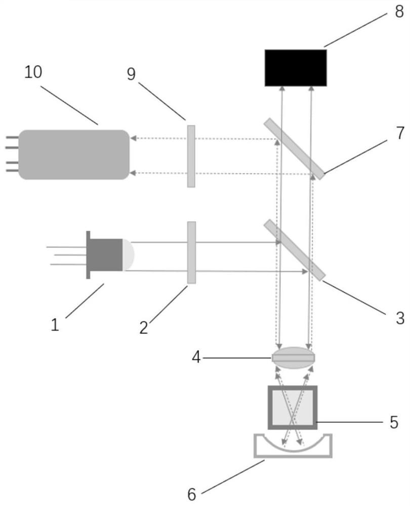
[0044] like figure 1 As shown, a fluorescence detector consists of an excitation light source 1, an excitation filter 2, a first dichroic mirror 3, a first converging lens 4, a detection cell 5, a curved mirror 6, and a second dichroic mirror 7 , a light trap 8, an emission filter 9 and a photodetector 10. The excitation light path of the fluorescence detector and the fluorescence emission light path form 180° with each other; the excitation light path is sequentially provided with an excitation light source 1, an excitation filter 2 and a first dichroic mirror 3, wherein the excitation light source 1 selects the central wavelength is a light-emitting diode of 365nm, its half-peak width is 15nm, and the divergence angle is 10°; the central wavelength of the excitation filter 2 is 365nm, and the bandwidth is 70nm; the first dichroic mirror 3 can reflect the excitation light and transmit Fluorescence and the angle between the excitation light path is 45°, the transmission band:...

Embodiment 2

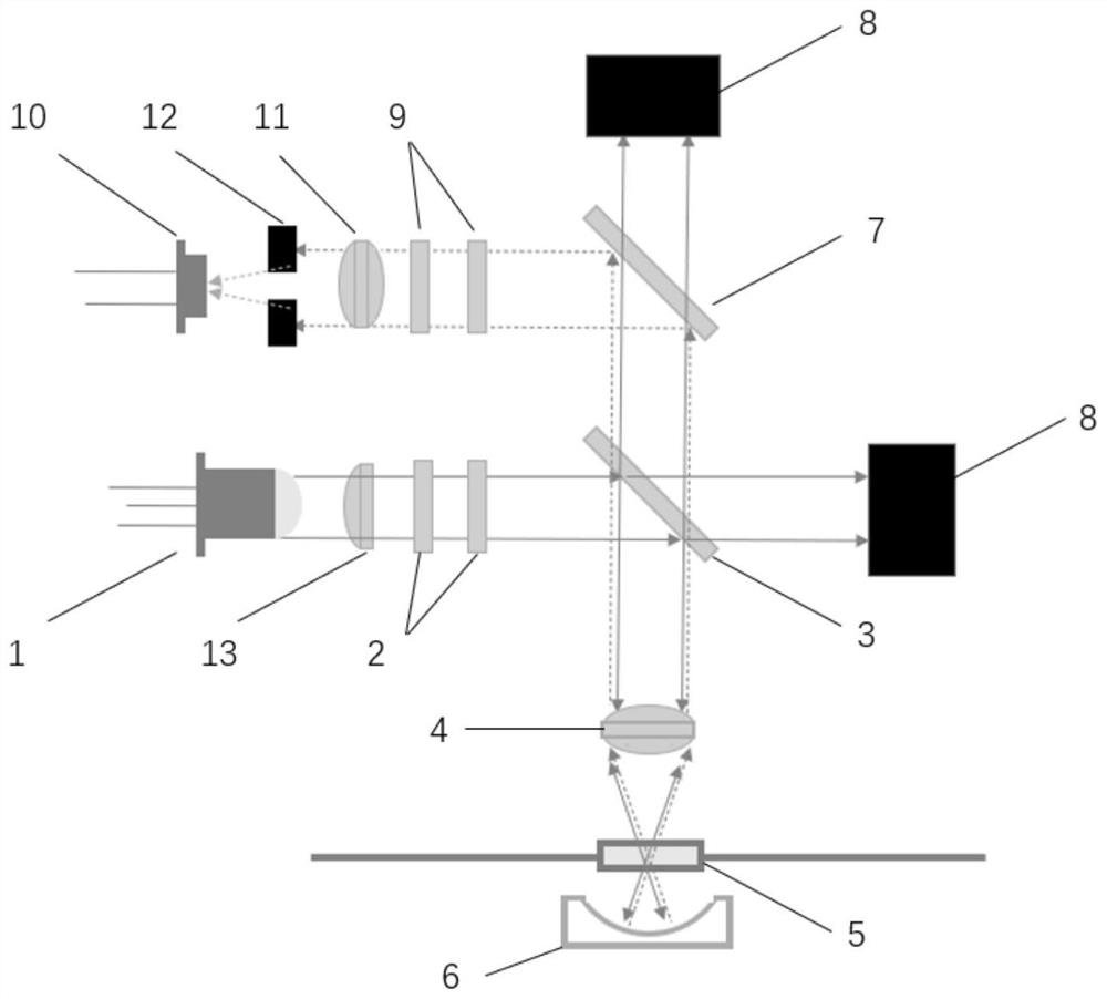
[0049] like figure 2 As shown, what is different from Embodiment 1 is that in this embodiment, the photodetector 10 is a photodiode, and the number of excitation filters 2 and emission filters 9 are both 2. A diaphragm 12 and a second converging lens 11 are arranged between the photodetectors 10, the diaphragm 12 is close to one end of the photodetector 10, and the aperture is 2.5 mm; There is a third converging lens 13; the detection pool 5 is a post-column detection pool, which is a quartz tube with an inner diameter of 2 mm, an outer diameter of 4 mm and a length of 7 mm; the optical trap 8 is provided with two, one is located in the first dichroic mirror 3 On the rear side, the excitation light passing through the first dichroic mirror 3 is vertically irradiated on it; the other is located on the rear side of the second dichroic mirror 7, and the excitation light and stray light passing through the second dichroic mirror 7 are vertically irradiated Above, the two light t...

Embodiment 3

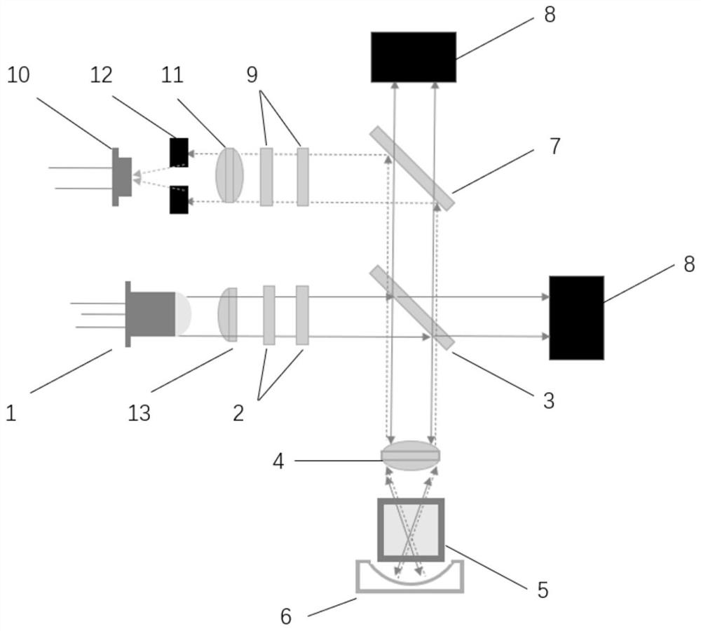
[0055] like image 3 As shown, the difference from Embodiment 2 is that in this embodiment, the detection cell 5 is a cuvette detection cell; the photodetector 10 is a charge-coupled element.


PUM

PropertyMeasurementUnit
wavelengthaaaaaaaaaa
radiusaaaaaaaaaa
lengthaaaaaaaaaa

Abstract

The invention provides a fluorescence detector. The fluorescence detector comprises an excitation light source, an excitation light filter, a first dichroscope, a first converging lens, a detection pool, a curved surface reflector, a second dichroscope, a light trap, an emission light filter and a photoelectric detector, the fluorescence detector adopts a collinear light path structure, fluorescence and unused exciting light are collected and reflected by a curved reflector, and the exciting light and stray light doped in the fluorescence are eliminated through a second dichroscope on a fluorescence emission light path and a light trap behind the second dichroscope. Therefore, on the premise that secondary utilization of the exciting light and efficient collection of the fluorescence are ensured, adverse effects of the exciting light and stray light which are reflected into the fluorescence emission light path by the curved surface reflector on the detection signal-to-noise ratio are avoided, and the detection signal-to-noise ratio can be improved by more than four times.

Description

technical field [0001] The present invention relates to the technical field of optical detection, in particular, to a fluorescence detector. Background technique [0002] Fluorescence detector is a detector with high selectivity and ultra-high sensitivity, which plays an important role in the detection of ultra-trace molecular level. The sensitivity of the detector is one of the important parameters to measure its performance. In order to improve the sensitivity, people usually optimize the fluorescence detector from the perspective of increasing the excitation light intensity and improving the fluorescence collection efficiency. In principle, the fluorescence generated by the excitation region illuminated by the excitation light is spatially divergent, and the detector can only collect the fluorescence at a small part of the angle, so the fluorescence collection efficiency is very low. In order to improve the collection efficiency of fluorescence, people arrange the curved...

Claims


Application Information

Patent Timeline
Patent Type & Authority Applications(China)
IPC IPC(8): G01N21/64G01N21/01
CPCG01N21/6428G01N21/645G01N21/01G01N2021/6463
Inventor 耿旭辉王传亮关亚风
Owner DALIAN INST OF CHEM PHYSICS CHINESE ACAD OF SCI
Learn More