
Supporting device and system of air cylinder and control method of supporting system

A support device and support system technology, which is applied in the direction of jet propulsion devices, gas turbine devices, machines/engines, etc., can solve the problem of non-adjustable support stiffness at the cold end of the intake cylinder, and quickly solve vibration problems, reduce operating risks, and reduce operating costs. Risk and Cost Effects

Pending Publication Date: 2022-05-27
CHINA UNITED GAS TURBINE TECH CO LTD
View PDF0 Cites 0 Cited by
  • Summary
  • Abstract
  • Description
  • Claims
  • Application Information

AI Technical Summary

Problems solved by technology

[0005] The main purpose of the present invention is to provide a new type of cylinder support device to solve the problem that the rigidity of the support at the cold end of the existing intake cylinder cannot be adjusted

Method used


Image

  • Supporting device and system of air cylinder and control method of supporting system
  • Supporting device and system of air cylinder and control method of supporting system
  • Supporting device and system of air cylinder and control method of supporting system

Examples


Embodiment 1

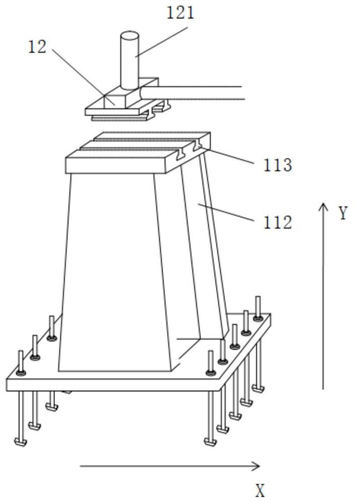
[0048] In the support assembly provided in the first embodiment, the first adjustment part is the first sliding adjustment part 12 , and the position of the first sliding adjustment part 12 on the support body can be adjusted continuously.

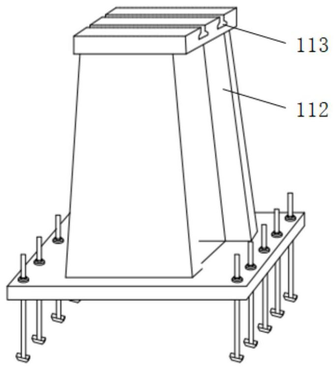
[0049] The third adjusting portion provided on the support body is the third sliding adjusting portion 113, and is provided with two or more inverted T-shaped and inverted trapezoidal sliding grooves. figure 2 The illustrated third sliding adjustment portion 113 is provided with two inverted T-shaped sliding grooves, and the sliding grooves run through the entire top plate. In the installation position of the support assembly, the chute is arranged in the horizontal direction. The corresponding first sliding adjustment portion 12 is provided with two inverted T-shaped sliding blocks, and the sliding blocks are arranged through the bottom plate of the first sliding adjustment portion 12 . The area of ​​the bottom plate of the first slidin...

Embodiment 2

[0053] The second embodiment provides a support assembly in which the position of the first adjustment portion on the support body can be adjusted intermittently. The first adjustment portion is the first intermittent adjustment portion 14, and the position of the first adjustment portion on the support body can be adjusted intermittently. .

[0054] The second embodiment changes the way of adjusting the position of the first adjusting portion on the basis of the first embodiment. like image 3 As shown, the third adjustment part on the support body is the third intermittent adjustment part 114, and is provided with a plurality of second holes 122, and the second holes 122 are threaded holes. like image 3 As shown, the second holes 122 are arranged in 5 rows in the horizontal direction, and each row has 3 holes; a plurality of first holes 111 are arranged on the bottom plate of the corresponding first intermittent adjustment part 14, and the first holes 111 are light holes ...


PUM


Abstract

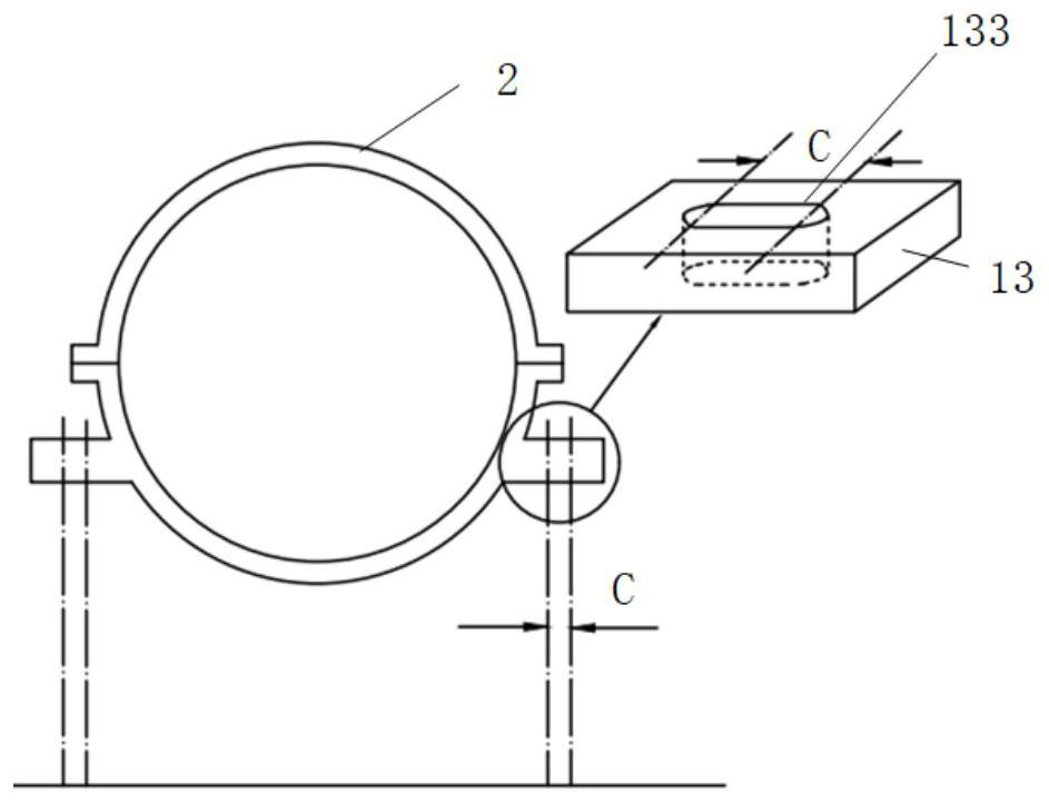
The invention discloses a gas turbine cylinder support device, the support device supports a cylinder (2), the support device at least comprises a support assembly, the support assembly comprises: a support body; the first adjusting parts (12 and 14) are arranged on the supporting body, and the positions of the first adjusting parts (12 and 14) on the supporting body are adjustable; and the second adjusting part (13) is used for accommodating the adjusting displacement of the first adjusting parts (12 and 14), and the second adjusting part (13) and the air cylinder (2) are integrally designed or fixedly connected. By adjusting the supporting rigidity of the air cylinder, an adjusting means is provided for solving the vibration problem of a gas turbine operation site. And when the vibration of the rotor system does not meet the requirement, the vibration problem can be solved by adjusting the supporting rigidity without reprocessing design, so that the operation risk and cost of the gas turbine are reduced.

Description

technical field [0001] The present invention relates to a gas turbine, in particular to a cold end support assembly for an inlet cylinder of a heavy-duty gas turbine. Background technique [0002] The gas turbine uses a continuous flow of gas as the working medium, and converts the heat energy of the working medium into mechanical work through rotary power. One of the main functions of gas turbine support is to provide sufficient support rigidity for the rotor to make the dynamic characteristics of the rotor system meet the requirements. It is divided into hot end support and cold end support. The hot end support is located on the turbine side and mainly bears the turbine end components. Weight; the cold end support is arranged on both sides of the cylinder block of the intake cylinder and mainly bears the weight of the compressor end components. The support stiffness is not only related to the structural strength of the support assembly itself, but also to the distance betw...

Claims


Application Information

Patent Timeline
Patent Type & Authority Applications(China)
IPC IPC(8): F02C7/20
CPCF02C7/20
Inventor 宋慧斌孙晓谢意
Owner CHINA UNITED GAS TURBINE TECH CO LTD
Learn More