Large aircraft temperature shock test device and test method
An impact test and aircraft technology, applied in the field of aircraft test and test, can solve the problems of high failure rate, difficult design, and lack of ability to carry out temperature shock test, and achieve the effects of low cost, easy implementation and short construction period
- Summary
- Abstract
- Description
- Claims
- Application Information
AI Technical Summary
Problems solved by technology
Method used
Image
Examples
Embodiment 1
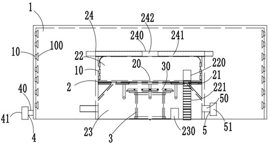
[0037] like figure 1 A large-scale aircraft temperature shock test device as shown includes a climate laboratory chamber 1 for simulating a low temperature environment, an environment chamber 2 arranged in the climate laboratory chamber 1 and used for simulating a high temperature environment, and an environment chamber 2. The hydraulic lift assembly 3 in 2, the low temperature control assembly 4 communicated with the climate laboratory chamber 1, and the high temperature control assembly 5 communicated with the environment chamber 2;
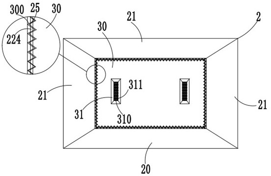
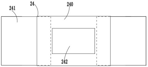
[0038] like figure 2 As shown, each side wall of the environmental compartment 2 is respectively provided with a fixed platform 20 and three reversible mobile platforms 21 for test operation, and the interior of the environmental compartment 2 can be divided into an upper cabin 22 through the fixed platform 20 and the mobile platform 21 and the lower cabin 23, an upper isolation door 220 is provided on the side wall of the upper cabin 22 and ...
Embodiment 2
[0044] This embodiment is basically the same as Embodiment 1, except that:
[0045] like Figure 4 As shown, the inner wall of the climate laboratory chamber 1 is evenly provided with a plurality of first installation grooves 11, and each first installation groove 11 is clamped with a first stainless steel patch 12, and the inner wall of the upper cabin 22 is evenly provided with There are a plurality of second installation grooves 222 , and a second stainless steel patch 223 is clamped in each of the second installation grooves 222 , and each air outlet 10 is provided with an air diffuser 100 .
Embodiment 3
[0047] This embodiment is basically the same as Embodiment 2, except that:
[0048] like figure 2 As shown, a plurality of first insertion limit teeth 300 are evenly arranged on the surrounding side walls of the lifting platform 30, and the side walls of the fixed platform 20 and the mobile platform 21 are provided with first insertion limit teeth 300 staggered distribution. Two insertion limit teeth 25, each side wall of the upper cabin body 22 is provided with horizontal fixed insertion rods 224, and the first insertion limit teeth 300 and the second insertion limit teeth 25 distributed in a staggered manner pass through the horizontal The fixed plunger 224 is connected.
PUM
 Abstract
Description
Claims
Application Information
 - R&D Engineer
- R&D Manager
- IP Professional
- Industry Leading Data Capabilities
- Powerful AI technology
- Patent DNA Extraction
Browse by: Latest US Patents, China's latest patents, Technical Efficacy Thesaurus, Application Domain, Technology Topic, Popular Technical Reports.
© 2024 PatSnap. All rights reserved.Legal|Privacy policy|Modern Slavery Act Transparency Statement|Sitemap|About US| Contact US: help@patsnap.com


