
Braking method, braking system and vehicle

A braking system and vehicle technology, applied in the field of vehicles, can solve problems such as difficulty in providing sufficient braking force, high vehicle configuration requirements, and unreliable braking, and achieve improved braking safety, simple system, and braking response fast effect

Active Publication Date: 2022-05-27
BYD CO LTD
View PDF5 Cites 3 Cited by
  • Summary
  • Abstract
  • Description
  • Claims
  • Application Information

AI Technical Summary

Problems solved by technology

[0003] In the existing technology, the coordination of vehicle control module, ESC (Electronic Stability Control, electronic stability control system) emergency braking module, feedback emergency braking module, and EPB (Electrical Park Brake, electronic parking brake module) is usually used. It is used to realize emergency braking, the system is complex, and it is easy to cause system failures, and it has high requirements for vehicle configuration (ESC configuration is required, which cannot be realized only with ABS configuration)
Moreover, it is difficult to provide sufficient braking force and reliable braking under certain special circumstances (brake system pipeline leakage, brake stuck or vehicle overload), and it is even difficult to activate the vehicle's ABS (Anti-Lock Braking System, anti-lock brake module), causing the safety hazard of vehicle wheel lock

Method used


Image

  • Braking method, braking system and vehicle
  • Braking method, braking system and vehicle
  • Braking method, braking system and vehicle

Examples


Embodiment Construction

[0024] In order to make the above objects, features and advantages of the present invention more clearly understood, the present invention will be described in further detail below with reference to the accompanying drawings and specific embodiments.

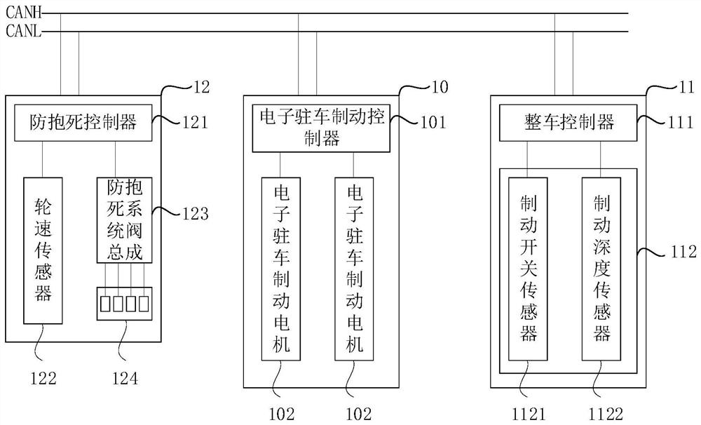
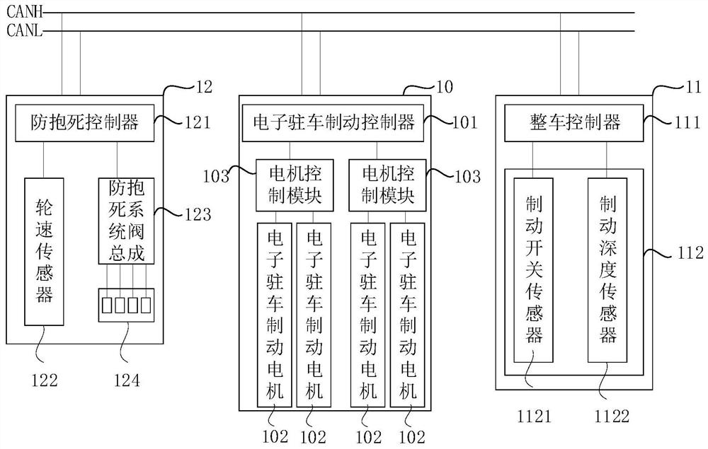
[0025] refer to figure 1 , showing a schematic diagram of the mechanism of a braking system according to an embodiment of the present invention, such as figure 1 As shown, the braking system includes: an electronic parking brake module 10 , a vehicle control module 11 and an anti-lock module 12 , the electronic parking brake module 10 , the vehicle control module 11 and the anti-lock module 12 pass through bus communication connection.

[0026] Specifically, the vehicle control module 11 may include: a vehicle controller 111 and a brake sensor 112 electrically connected to the vehicle controller 111 . The brake sensor 112 may be used to obtain a braking demand value, and the vehicle controller 111 may It is used to determine t...


PUM


Abstract

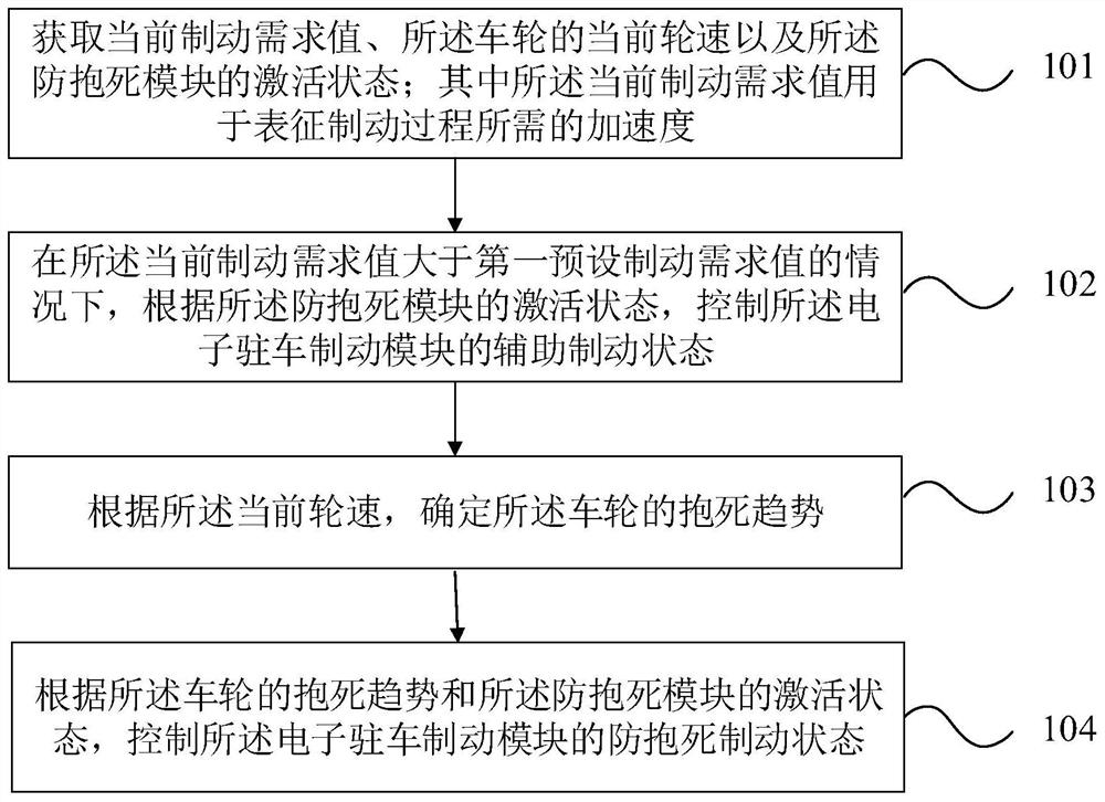
The embodiment of the invention provides a braking method, a braking system and a vehicle, the braking method is used for the vehicle, the vehicle comprises wheels, an anti-lock module and an electronic parking braking module, and the braking method comprises the steps that the current braking demand value, the current wheel speed of the wheels and the activation state of the anti-lock module are obtained; wherein the current braking demand value is used for representing the acceleration required by the braking process; under the condition that the current braking demand value is larger than a first preset braking demand value, the auxiliary braking state of the electronic parking braking module is controlled according to the activation state of the anti-lock braking module; according to the current wheel speed, the locking trend of the wheel is determined; and according to the locking trend of the wheels and the activation state of the anti-locking module, the anti-locking braking state of the electronic parking braking module is controlled. In the embodiment of the invention, the dangerous working condition of wheel locking can be avoided while reliable braking of the vehicle is realized, and the braking safety of the vehicle is improved.

Description

technical field [0001] The present invention relates to the technical field of vehicles, and in particular, to a braking method, a braking system and a vehicle. Background technique [0002] Emergency braking refers to the braking method in which the driver quickly slams on the brake pedal and stops the car in the shortest distance when the car encounters an emergency during the driving process. The emergency braking performance of the vehicle directly affects the safety and braking stability of the vehicle, so it has received extensive attention. [0003] In the existing technology, the coordination of a vehicle control module, an ESC (Electronic Stability Control, electronic stability control system) emergency braking module, a feedback emergency braking module, and an EPB (Electrical Park Brake, electronic parking brake module) is usually used. It is used to realize emergency braking, the system is complex, and it is easy to cause system failures, and the configuration r...

Claims


Application Information

Patent Timeline
Patent Type & Authority Applications(China)
IPC IPC(8): B60T8/1755B60T8/32B60L7/00
CPCB60T8/1755B60T8/32B60L7/00Y02T10/72
Inventor 付永泉秦宬刘强陈俊勇高坚
Owner BYD CO LTD
Learn More