Method for estimating total braking force, braking equipment and commercial vehicles or combinations of vehicles

A vehicle combination and braking equipment technology, applied in the field of commercial vehicles or vehicle combination, can solve the problem of not being able to fully exploit the potential of fleet fuel consumption, and achieve the effect of simple construction

Active Publication Date: 2022-05-27
WABCO GMBH
View PDF9 Cites 0 Cited by
  • Summary
  • Abstract
  • Description
  • Claims
  • Application Information

AI Technical Summary

Problems solved by technology

In the absence of reliable information on the total achievable braking force, the potential of the fleet for reducing fuel consumption cannot be fully exploited

Method used


Image

  • Method for estimating total braking force, braking equipment and commercial vehicles or combinations of vehicles
  • Method for estimating total braking force, braking equipment and commercial vehicles or combinations of vehicles
  • Method for estimating total braking force, braking equipment and commercial vehicles or combinations of vehicles

Examples


Embodiment Construction

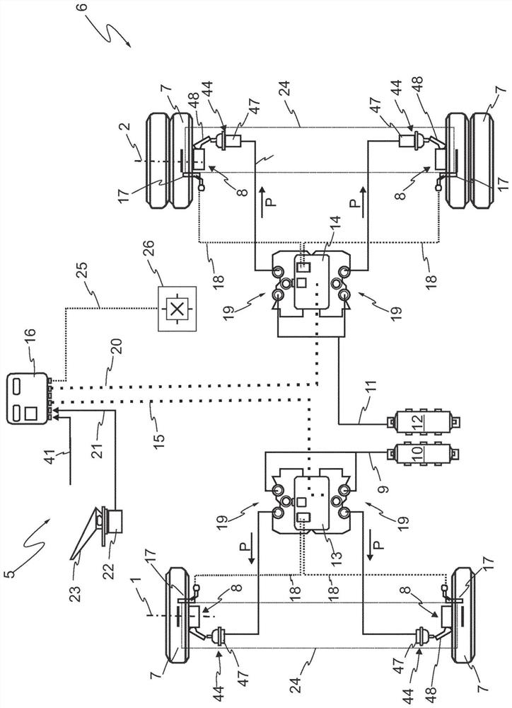
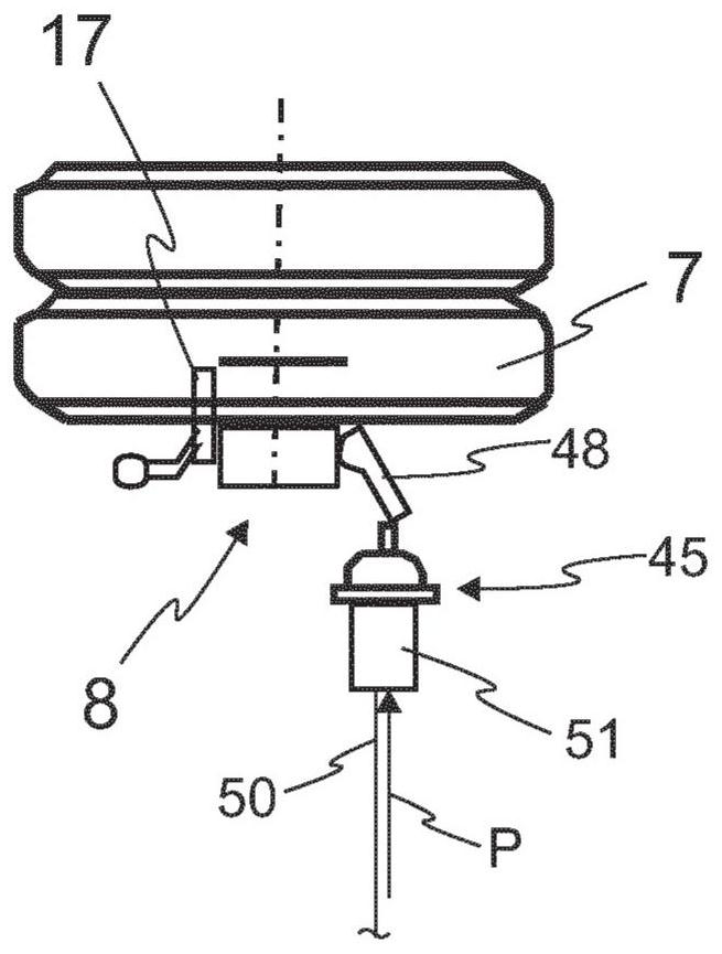
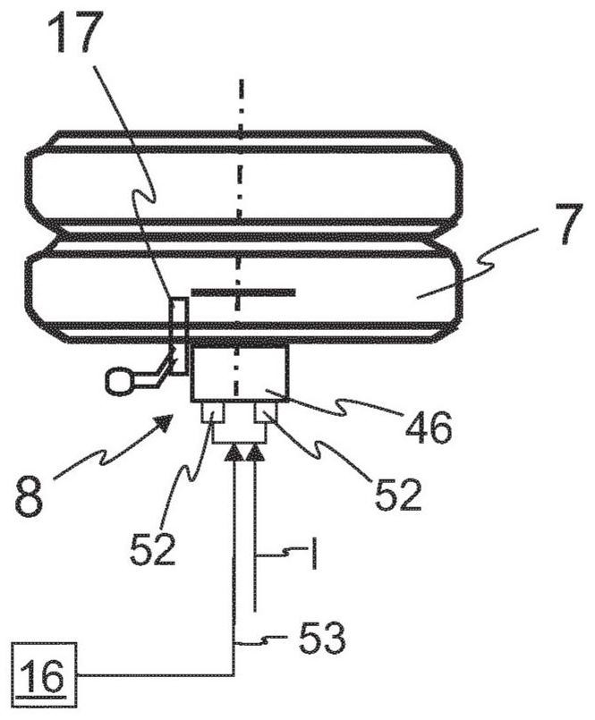
[0044] figure 1 A schematic diagram of the electropneumatics of the electronic braking system 5 of the commercial vehicle 6 is shown. Electrical lines are shown in dotted lines, and pneumatic lines are shown in solid lines. In the embodiment shown, the commercial vehicle 6 comprises two axles 1 , 2 on which wheels 7 are arranged on each side. In order to brake the commercial vehicle 6 , a wheel brake 8 is assigned to each wheel 7 . The wheel brakes 8 are embodied as disc brakes in the exemplary embodiment shown and are actuated by actuating systems 44 , 45 , 46 . on the basis of figure 1 In the exemplary embodiment, the braking device 5 has a pneumatic actuating system 44, so that the wheel brakes 8 are pneumatically actuable and apply a braking force to the wheel 7 which is rotating in accordance with the current braking pressure P. The pneumatic actuating system 44 consists of a pneumatic brake cylinder 47 connected to the wheel brake 8 , as well as a brake lever 48 and ...


PUM


Abstract

The present invention relates to the estimation of the achievable total braking force (F Ges ) method, in which the partial braking force is set via the control variables (P, I) on the respective wheel brake. The invention also relates to a braking device for carrying out the method, and to a commercial vehicle or a vehicle combination having such a braking device. According to the invention, the achievable total braking force for decelerating the commercial vehicle or vehicle combination is estimated as accurately as possible during continuous operation, wherein the braking unit ( 24 ) formed by at least one of the wheel brakes is evaluating the braking In the middle (29), the braking force (F a ). Here, the current deceleration (v) is determined from the measured value ( 25 ) and, taking into account the current deceleration (v), the current deceleration ( b) and the known or preset total mass (m tot ), the representative partial braking force (F) of the activated braking unit (24) is known B1 , F B2 , F B3 , F B4 ) and the braking characteristic value (C) of the ratio of the control parameters (P, I) set for this L1 ). From the known braking characteristic value (C L1 , C L2 , C L3 , C L4 ) deduces the partial braking force (F) that can be achieved by the respective braking unit (24) B1 , F B2 , F B3 , F B4 ). The total braking force that will be achieved (F Ges ) is estimated as the achievable partial braking force (F B1 , F B2 , F B3 , F B4 ) sum (31).

Description

technical field [0001] The present invention relates to a method for estimating the achievable total braking force for automated deceleration of a commercial vehicle or a vehicle combination with multiple axles. The invention furthermore relates to a braking system for carrying out the method, as well as to a commercial vehicle or a vehicle combination having such a braking system. Background technique [0002] Automated braking systems are increasingly used in modern commercial vehicles, for example advanced emergency braking systems (AEBS=“advanced emergency braking system”), driver assistance systems such as electronic stability control (ESC), in which braking The electronic brake control unit automatically decelerates the vehicle when required, independently of the driver's braking. It is particularly important here to know the available total braking force of the commercial vehicle as accurately as possible. This applies in particular to so-called convoys, in which se...

Claims


Application Information

Patent Timeline
Patent Type & Authority Patents(China)
IPC IPC(8): B60T8/17B60T8/172
CPCB60T8/1708B60T8/172B60T2250/02B60T7/12
Inventor 克里斯蒂安·维恩
Owner WABCO GMBH
Why Eureka
Try Eureka