Method for estimating the achievable total braking forces for the automated deceleration of a utility vehicle, braking system and utility vehicle having said braking system
What is Al technical title?
Al technical title is built by PatSnap Al team. It summarizes the technical point description of the patent document.
A technology of braking equipment and total braking force, which is applied in the field of commercial vehicles or vehicle combinations, and can solve problems such as the inability to fully explore the potential of fleet fuel consumption
Active Publication Date: 2020-01-07
WABCO GMBH
View PDF9 Cites 0 Cited by
Summary
Abstract
Description
Claims
Application Information
AI Technical Summary
This helps you quickly interpret patents by identifying the three key elements:
Problems solved by technology
Method used
Benefits of technology
Problems solved by technology
In the absence of reliable information on the total achievable braking force, the potential of the fleet for reducing fuel consumption cannot be fully exploited
Method used
Image
Click on the blue label to locate the original text in one second.
Reading with bidirectional positioning of images and text.
Examples
Embodiment Construction
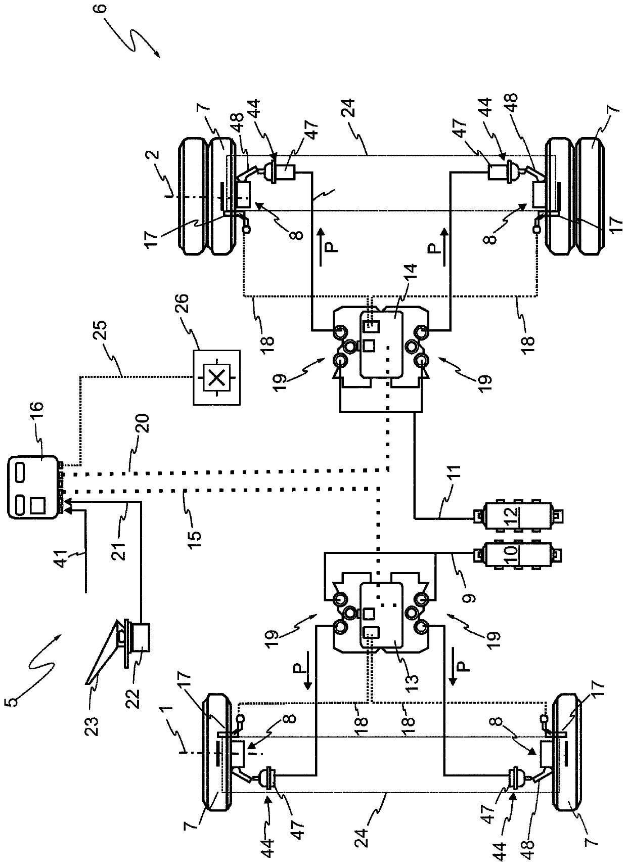
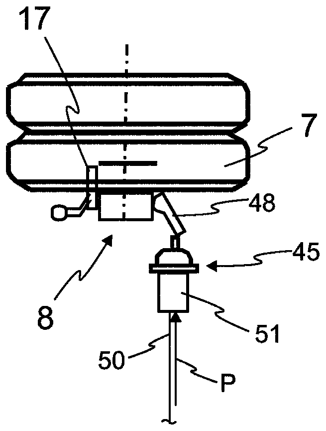
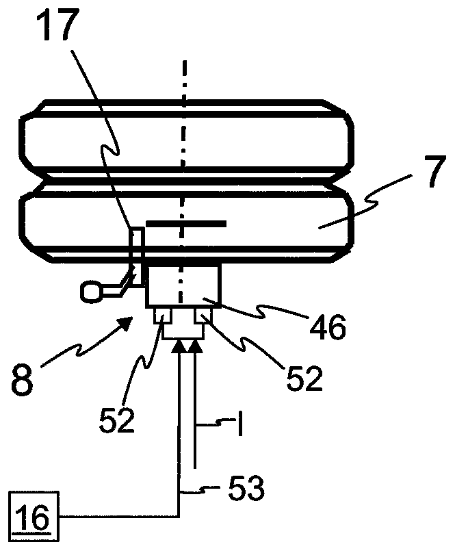
[0044] figure 1 A schematic diagram of the electropneumatics of an electronic brake system 5 of a commercial vehicle 6 is shown. Electrical circuits are shown in dotted lines and pneumatic circuits are shown in solid lines. In the exemplary embodiment shown, the commercial vehicle 6 comprises two axles 1 , 2 on which wheels 7 are respectively arranged on both sides. To brake the commercial vehicle 6 , a wheel brake 8 is assigned to each wheel 7 . In the exemplary embodiment shown, wheel brakes 8 are designed as disc brakes and are operated via actuation systems 44 , 45 , 46 . in accordance with figure 1 In the embodiment of the present invention, the brake system 5 has a pneumatic actuation system 44, so that the wheel brakes 8 are pneumatically actuated and, depending on the current brake pressure P, exert a braking force on the rotating wheels 7 themselves. The pneumatic actuation system 44 is formed by a pneumatic brake cylinder 47 connected to the wheel brake 8 as well...
PUM
Abstract
The invention relates to a method for estimating the achievable total braking forces (FGes) for the automated deceleration of a utility vehicle or of a vehicle combination having a plurality of axles,partial braking forces being set at each wheel brake by means of a manipulated variable (P, I). The invention also relates to a braking system for carrying out the method and to a utility vehicle ora vehicle combination having such a braking system. According to the invention, the achievable total braking forces for the deceleration of a utility vehicle or of a vehicle combination are estimatedas accurately as possible during ongoing operation, in that brake units (24) consisting of at least one of the wheel brakes at least partially apply a braking force (Fa) required for deceleration, each as the only active braking unit (24), in estimation braking operations (29). The current deceleration (v) is determined from measurement values (25), and, taking into consideration the current deceleration (v), a braking parameter (CL1) of the active braking unit (24), representing the ratio of the partial braking force (FB1, FB2, FB3, FB4) and the manipulated variable (P, I) set therefor, is determined, taking into consideration the current deceleration (b) and a determined or specified total mass (mtot) of the utility vehicle (6) or of the vehicle combination (27). From the determined braking parameter (CL1, CL2, CL3, CL4), a conclusion about the partial braking forces (FB1, FB2, FB3, FB4) achievable by the respective braking units (24) is drawn. The achievable total braking forces (FGes) are estimated as a sum (31) of the achievable partial braking forces (FB1, FB2, FB3, FB4).
Description
technical field [0001] The invention relates to a method according to claim 1 for estimating an achievable total braking force for automated deceleration of a commercial vehicle or a vehicle combination with several axles. The invention furthermore relates to a brake system for carrying out the method according to claim 9 and to a commercial vehicle or a combination of vehicles according to claim 11 having such a brake system. Background technique [0002] Automated braking systems, such as advanced emergency braking systems (AEBS = "advanced emergency braking system"), driver assistance systems such as electronic stability control (ESC), are increasingly used in modern commercial vehicles, wherein braking The electronic brake control unit automatically decelerates the vehicle when required independently of the driver's braking. It is particularly important here to know the available total braking force of the commercial vehicle as accurately as possible. This applies in p...
Claims
Application Information
Patent Timeline
Application Date:The date an application was filed.
Publication Date:The date a patent or application was officially published.
First Publication Date:The earliest publication date of a patent with the same application number.
Issue Date:Publication date of the patent grant document.
PCT Entry Date:The Entry date of PCT National Phase.
Estimated Expiry Date:The statutory expiry date of a patent right according to the Patent Law, and it is the longest term of protection that the patent right can achieve without the termination of the patent right due to other reasons(Term extension factor has been taken into account ).
Invalid Date:Actual expiry date is based on effective date or publication date of legal transaction data of invalid patent.