Injection molding equipment for vehicle-mounted electronic product processing

A technology of injection molding and on-board electronics, which is applied in applications, household appliances, household components, etc., can solve problems such as troubles, and achieve the effect of fast cooling molding

Pending Publication Date: 2022-05-24
深圳市凯迪炫电子科技有限公司
View PDF1 Cites 0 Cited by
  • Summary
  • Abstract
  • Description
  • Claims
  • Application Information

AI Technical Summary

Problems solved by technology

[0005] In order to overcome the disadvantage that the existing injection molding device needs to manually take out the finished product from the mold after use, the purpose of the present invention is to provide an injection molding equipment for vehicle-mounted electronic products that can automatically discharge the finished product

Method used


Image

  • Injection molding equipment for vehicle-mounted electronic product processing
  • Injection molding equipment for vehicle-mounted electronic product processing
  • Injection molding equipment for vehicle-mounted electronic product processing

Examples


Embodiment 1

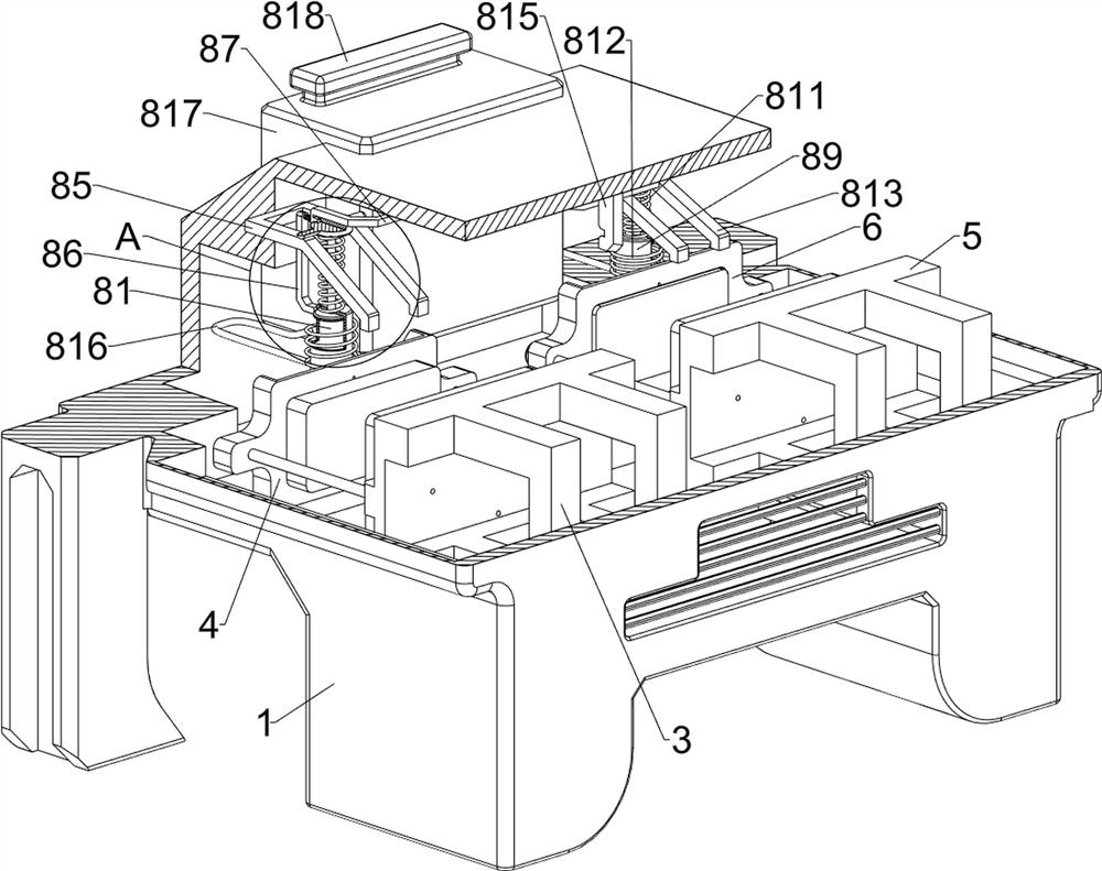
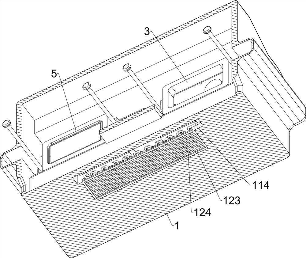
[0040] An injection molding equipment for automotive electronic product processing, refer to Figure 1-Figure 14 , including a shell 1, a discharge plate 2, a first lower mold 3, a first upper mold 4, a second lower mold 5, a second upper mold 6, a push assembly 7, a feed assembly 8 and a discharge assembly 9, the shell 1. There is a discharge plate 2 in the middle of the left and right sides of the lower part, and a first lower mold 3 is welded on the upper right rear side of the inner shell 1. The front part of the first lower mold 3 is slidingly provided with a first upper mold 4. A second lower mold 5 is welded on the upper left rear side of the inner side. The front of the second lower mold 5 is slidably provided with a second upper mold 6. When the raw material is transferred between the first lower mold 3 and the first upper mold 4 and After the second lower mold 5 and the second upper mold 6 are between the second lower mold 5 and the second upper mold 6, wait for the ...

Embodiment 2

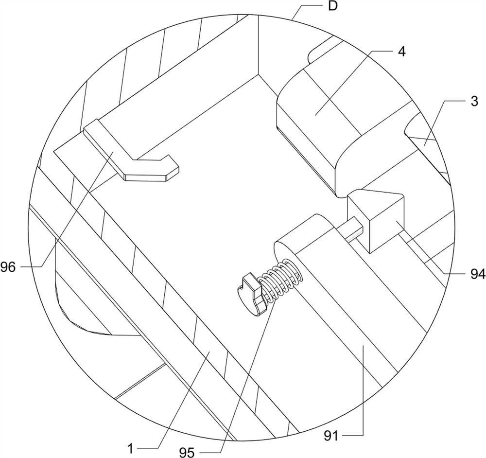
[0046] On the basis of Example 1, refer to figure 2 and Figure 15 , and also includes a disengagement assembly 10, the disengagement assembly 10 includes a fifth link 101, a third push rod 102 and an eighth spring 103, the top of the third link 92 is provided with a fifth link 101, the first lower mold 3 A third push rod 102 is slidably provided between the upper front side of the second lower die 5 and the upper front side of the second lower mold 5. When the third push rod 102 moves downward, the finished product can be pushed down, and the fifth link 101 moves forward. The movement will be in contact with the third push rod 102 , and two eighth springs 103 are provided between the first lower mold 3 and the second lower mold 5 and the third push rod 102 .

[0047] When the third link 92 moves forward, it drives the fifth link 101 to move forward, the fifth link 101 squeezes the third push rod 102 to move downward, and the eighth spring 103 compresses. Both the rod 91 and ...


PUM


Abstract

The invention relates to injection molding equipment, in particular to injection molding equipment for vehicle-mounted electronic product processing. The invention aims to provide the injection molding equipment for vehicle-mounted electronic product processing, which can automatically discharge finished products. The injection molding equipment for vehicle-mounted electronic product processing comprises a shell, discharging plates, a first lower mold, a first upper mold, a second lower mold, a second upper mold and the like, the discharging plates are arranged in the middles of the left side and the right side of the lower portion of the shell, the first lower mold is arranged on the right rear side of the upper portion of the inner side of the shell, and the first upper mold is arranged on the front portion of the first lower mold in a sliding mode; a second lower die is arranged on the left rear side of the upper portion of the inner side of the shell, and a second upper die is slidably arranged on the front portion of the second lower die. When the first upper die moves forwards, the first push rod and the second push rod can be driven to move forwards, so that a finished product can be pushed forwards, the automatic discharging function is completed, and time and labor are saved.

Description

technical field [0001] The invention relates to an injection molding device, in particular to an injection molding device for processing vehicle-mounted electronic products. Background technique [0002] During the processing of automotive electronic products, some parts need to be injection-molded, but the current injection-molding device generally processes a single part, and it needs to be injected one by one during the injection molding process, so the work efficiency is not high. [0003] Patent application CN213500442U, published on 20210622, discloses an injection molding device for automotive electronic product processing, comprising a base and an annular plate above the base, the annular plate and the base are connected by a plurality of evenly distributed struts, the annular plate The upper surface of the base is fixedly installed with a plurality of lower molds uniformly distributed in a ring shape, a support cylinder with a hollow structure is fixedly connected t...

Claims


Application Information

Patent Timeline
Patent Type & Authority Applications(China)
IPC IPC(8): B29C45/67B29C45/73B29C45/40B29C45/17B29C45/12B29L31/30
CPCB29C45/67B29C45/73B29C45/4005B29C45/17B29C45/12B29L2031/3005
Inventor 郭琴
Owner 深圳市凯迪炫电子科技有限公司
Why Eureka
Try Eureka