
Flexible assembly type line forming machine

A prefabricated, forming machine technology, applied in the direction of grinding frames, grinding machine parts, grinding/polishing safety devices, etc., can solve the problems of prolonging the operation time, increasing the difficulty of the operation, and increasing the labor cost, etc. Achieve the effect of reducing difficulty, stable movement, and fast fine-tuning speed

Active Publication Date: 2022-05-24
九江聚鸿新材料有限公司
View PDF8 Cites 0 Cited by
  • Summary
  • Abstract
  • Description
  • Claims
  • Application Information

AI Technical Summary

Problems solved by technology

[0005] Aiming at the deficiencies of the prior art, the present invention provides a flexible assembly type line forming machine, which solves the problem that the existing line forming machine needs to be replaced when grinding lines in batches. For arc-shaped and shaped grinding sheets, it is necessary to remove multiple sets of grinding sheets one by one and replace them with corresponding grinding sheets, which increases the difficulty of operation to a certain extent and prolongs the operation time. After grinding, the surface of the workbench will be contaminated with a lot of debris and dust. In order to ensure the normal grinding of the lines and the thickness of the lines obtained after grinding (the debris and dust accumulated on the surface of the workbench will raise the line to be polished to a certain extent) The height of the surface of the workbench), after polishing a set of lines, it is necessary to clean the debris and dust on the surface of the workbench, which not only reduces the work efficiency to a certain extent, but also increases the problem of labor costs

Method used


Image

  • Flexible assembly type line forming machine
  • Flexible assembly type line forming machine
  • Flexible assembly type line forming machine

Examples


Embodiment Construction

[0028] To make the object, technical solution and advantages of embodiments of the present invention more clear, the following will be combined with the accompanying drawings in the embodiments of the present invention, the technical solutions in the embodiments of the present invention are clearly and completely described, obviously, the embodiments described are part of the embodiments of the present invention, not all embodiments. Based on embodiments in the present invention, all other embodiments obtained by those of ordinary skill in the art without making creative labor, are within the scope of protection of the present invention.

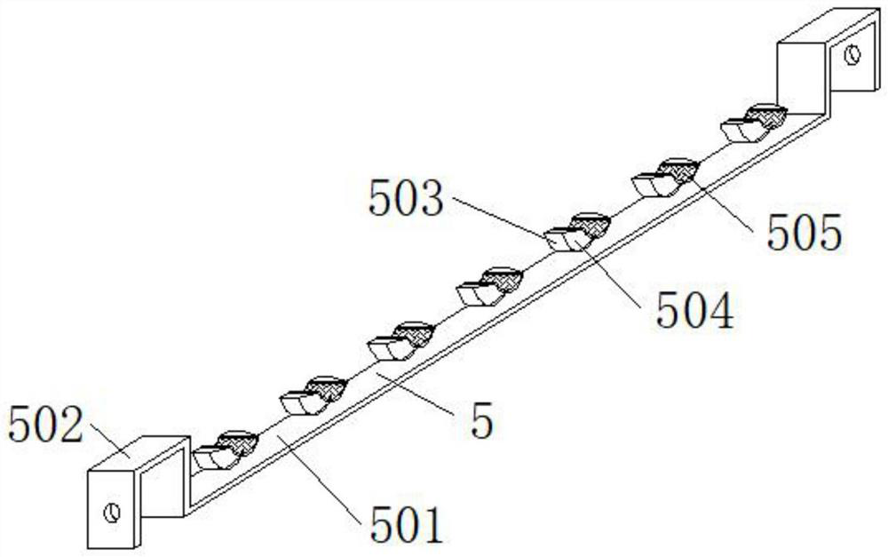
[0029] See Figure 1-9: A flexible assembly line forming machine, including the structure body 1, the structural body 1 is provided with side frame 2 at both ends, the top of the inner side of the side frame 2 is equipped with electromagnetic slide 3, the two groups of side frames 2 adjacent to one end are evenly set with multiple sets of placeme...


PUM


Abstract

The invention relates to the technical field of line forming, and discloses a flexible assembly type line forming machine which comprises a structure main body, side frames are arranged at the two ends of the structure main body correspondingly, electromagnetic sliding rails are installed at the top ends of the inner sides of the side frames correspondingly, and multiple sets of containing frames are evenly arranged at the adjacent ends of the two sets of side frames; and limiting assemblies are placed at the tops of the placing frames. According to the invention, since only the top of a roller is provided with a second latch, when the roller is influenced by a rotating shaft to rotate to the lower part and is in contact with a first latch at the bottom end in a movable hole, a sleeve rod is driven to move reversely until one side of the sleeve rod extends into a sleeve, so that the distance between an upper pressing frame and a U-shaped bracket is prolonged; therefore, the distance between the upper pressing frame and the workbench can be finely adjusted only by rotating the handle in the same direction, the adjustment direction does not need to be changed, the operation difficulty is lowered, meanwhile, the fine adjustment speed of the position of the upper pressing frame is higher, and the U-shaped support moves more stably.

Description

Technical field [0001] The present invention relates to the field of line forming technology, specifically a flexible assembly type line forming machine. Background [0002] Classification of line materials: stone wire, plaster line, wood line, plaster line, metal line, pvc line, tile line, resin line, etc. [0003] However, the existing line forming machine in the process of grinding the line, if the batch line is sanded, the middle needs to replace the grinding pieces of different arcs and shapes, it is necessary to remove multiple groups of grinding pieces in turn one by one, and replace the corresponding grinding pieces that need to be used, thus increasing the difficulty of the operation to a certain extent, prolonging the operation time, and the surface of the table will be contaminated with a large amount of debris and dust after each line grinding, in order to ensure the normal grinding of the line and the line thickness obtained after grinding is consistent ( The debris ...

Claims


Application Information

Patent Timeline
Patent Type & Authority Applications(China)
IPC IPC(8): B24B27/00B24B55/06B24B41/00B24B41/02
CPCB24B27/0076B24B27/0092B24B55/06B24B41/00B24B41/02Y02P70/10
Inventor 涂晟叶磊
Owner 九江聚鸿新材料有限公司
Learn More