Clutch device of wheel excavator

A technology for clutch devices and excavators, which is applied in the direction of non-mechanical drive clutches, clutches, control devices, etc., and can solve problems that affect work efficiency and operator fatigue

Pending Publication Date: 2022-05-17
龙岩市万通机械有限公司
View PDF0 Cites 0 Cited by
  • Summary
  • Abstract
  • Description
  • Claims
  • Application Information

AI Technical Summary

Problems solved by technology

Therefore, a large force is required to step on the pedal device. Therefore, during long-term use, especially in a working environment that requires frequent clutches and gears, it is easy to cause operator fatigue, thereby affecting work efficiency.

Method used


Image

  • Clutch device of wheel excavator
  • Clutch device of wheel excavator
  • Clutch device of wheel excavator

Examples


Embodiment Construction

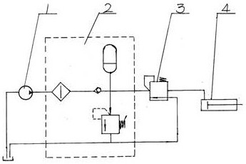
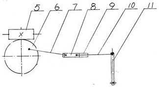
[0016] attached figure 1 And attached figure 2 A wheeled excavator clutch device according to the present invention includes a clutch and a clutch swing arm 11, the clutch is connected to one end of the clutch swing arm 11 through a fork lever, and the other end of the clutch swing arm 11 is connected to a separation device, and the separation device is Clutch separation oil cylinder 4, clutch separation oil cylinder 4 is also connected to one end of proportional valve 3 through a pipeline, the other end of proportional valve 3 is connected to one end of pilot oil source valve 2 through a pipeline, and the other end of pilot oil source valve 2 is connected to oil pump 1 through a pipeline, proportional The switch on the valve 3 is in contact with the pedal device arranged in the cab; the proportional valve 3 is a pedal proportional valve.

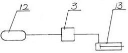
[0017] attached figure 2 A wheeled excavator clutch device shown can also include a clutch and a clutch swing arm 11, the clutch is co...


PUM


Abstract

The invention discloses a clutch device of a wheel excavator, and aims to solve the problems that in the long-term use process of an existing clutch device of the wheel excavator, particularly in the working environment needing frequent clutch gear engaging, operators are prone to fatigue, and therefore the working efficiency is affected. The separation device is a clutch separation oil cylinder (4), the clutch separation oil cylinder (4) is further connected with one end of a proportional valve (3) through a pipeline, the other end of the proportional valve (3) is connected with one end of a pilot oil source valve (2) through a pipeline, the other end of the pilot oil source valve (2) is connected with an oil pump through a pipeline, and a switch on the proportional valve (3) is in contact with a pedal device arranged in a cab.

Description

technical field [0001] The invention relates to a wheeled excavator, in particular to a wheeled excavator clutch device composed of a clutch and a clutch swing arm. Background technique [0002] At present, such a wheeled excavator clutch device is disclosed on the market. Its structural characteristics are: it includes a clutch and a clutch swing arm, the clutch is connected to one end of the clutch swing arm through a fork lever, and the other end of the clutch swing arm is connected to one end of the separation device. , the separation device is a clutch separation oil cylinder, the other end of the clutch separation oil cylinder is connected to one end of the push-pull oil cylinder through the oil pipe, and the other end of the push-pull oil cylinder is connected through the cab to the pedal device installed in the cab, and the oil inlet on the push-pull oil cylinder Connect to clutch fluid reservoir. Therefore, it takes a lot of power to step on the pedal device, so in...

Claims


Application Information

Patent Timeline
Patent Type & Authority Applications(China)
IPC IPC(8): F16D25/12F16D28/00F15B11/08F15B11/06B60K23/02
CPCF16D25/12F16D28/00F15B11/08F15B11/06B60K23/02
Inventor 陈楚龚新生陈光星
Owner 龙岩市万通机械有限公司
Why Eureka
Try Eureka