Eureka AIR delivers breakthrough ideas for toughest innovation challenges, trusted by R&D personnel around the world.

Fuel cell stack manifold structure

A technology of fuel cell stacks and manifolds, applied in fuel cells, circuits, electrical components, etc., can solve the problems of large space occupation, complex structure, and low integration, and achieve the goals of small space occupation, reduced consumption, and increased power Effect

Pending Publication Date: 2022-05-13
佛山仙湖实验室
View PDF12 Cites 1 Cited by
  • Summary
  • Abstract
  • Description
  • Claims
  • Application Information

AI Technical Summary

Problems solved by technology

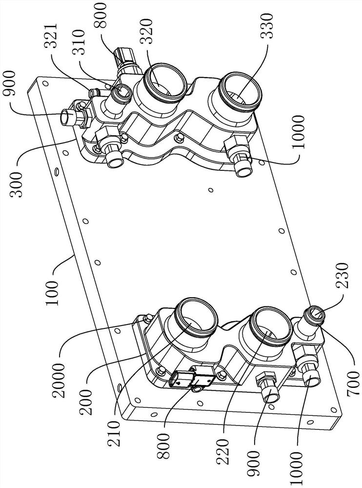
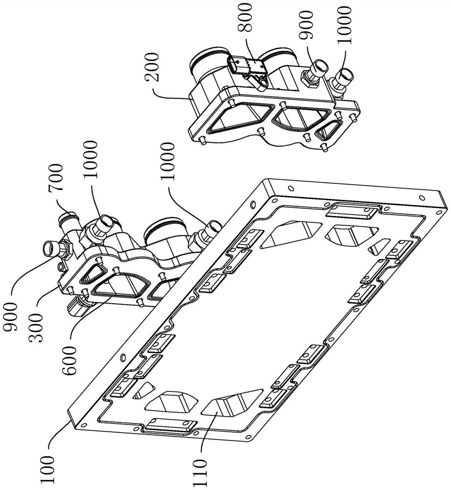
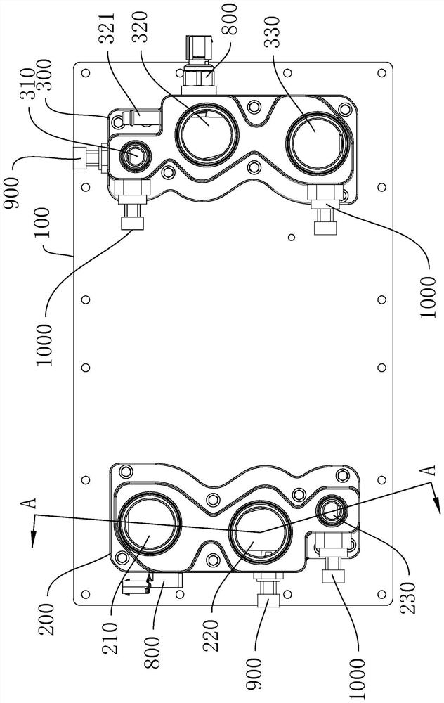
Among them, the fuel cell manifold is mainly used as the interface between gas and coolant, located on the end plate of the stack, and used for the import and export of hydrogen, air, and coolant. The existing manifold structure is low in integration, complex in structure, and takes up a lot of space. Large pressure loss

Method used


Image

  • Fuel cell stack manifold structure
  • Fuel cell stack manifold structure
  • Fuel cell stack manifold structure

Examples


Embodiment Construction

[0022] This part will describe the specific embodiment of the present invention in detail, and the preferred embodiment of the present invention is shown in the accompanying drawings. Each technical feature and overall technical solution of the invention, but it should not be understood as a limitation on the protection scope of the present invention.

[0023] In the description of the present invention, it should be understood that the orientation descriptions, such as up, down, front, back, left, right, etc. indicated orientations or positional relationships are based on the orientations or positional relationships shown in the drawings, and are only In order to facilitate the description of the present invention and simplify the description, it does not indicate or imply that the device or element referred to must have a specific orientation, be constructed and operated in a specific orientation, and thus should not be construed as limiting the present invention.

[0024] I...


PUM


Abstract

The invention discloses a fuel cell stack manifold structure, which comprises a stack end plate, a left box body and a right box body, the left box body and the right box body are arranged on the front wall surface of the stack end plate, the left box body is provided with three left channels, the three left channels comprise an air inlet channel, a cooling liquid inflow channel and a hydrogen discharge channel, and the right box body is provided with three right channels, the three right channels comprise a hydrogen inlet channel, a cooling liquid outflow channel and an air exhaust channel, the pile end plate is provided with a plurality of end plate ports communicated with all the channels, the left channel and the right channels each comprise a straight-through drainage basin section and a transition drainage basin section which are communicated front and back, and the straight-through drainage basin sections are of a straight-flow type channel structure with the same inner diameter. The transition drainage basin section is of a horn type channel structure with the inner diameter gradually increased from front to back. Therefore, the pressure drop between the front port of each channel and the port of the end plate can be reduced, that is, the power consumption of the system caused by the pressure drop of the manifold part is effectively reduced, the power of the system is further improved, and the pressure loss is reduced.

Description

technical field [0001] The invention relates to the technical field of fuel cells, in particular to a fuel cell stack manifold structure. Background technique [0002] Proton exchange membrane fuel cells have attracted much attention in the past two decades due to their advantages of low operating temperature and high power density. Among them, the fuel cell manifold is mainly used as the interface between gas and coolant, located on the end plate of the stack, and used for the import and export of hydrogen, air, and coolant. The existing manifold structure is low in integration, complex in structure, and takes up a lot of space. Large pressure loss. Contents of the invention [0003] The purpose of the present invention is to provide a fuel cell stack manifold structure to solve one or more technical problems in the prior art, and at least provide a beneficial option or create conditions. [0004] The technical solution adopted for solving the above-mentioned technical ...

Claims


Application Information

Patent Timeline
Patent Type & Authority Applications(China)
IPC IPC(8): H01M8/2483H01M8/2484
CPCH01M8/2483H01M8/2484Y02E60/50
Inventor 向蔚潘牧詹志刚郭伟戈琛范卫东洪丰汤歌尘梅坚张立昌
Owner 佛山仙湖实验室
Why Eureka
Eureka Blog
Learn More