
Fuel cell air supply system and control method

An air supply and fuel cell technology, which is applied in the fields of fuel cells, fuel cell additives, and reactant parameter control, and can solve the problems of difficult filtration of harmful gases, reduction of filter efficiency and lifespan, etc.

Pending Publication Date: 2022-05-13
CHINA COAL RES INST
View PDF8 Cites 0 Cited by
  • Summary
  • Abstract
  • Description
  • Claims
  • Application Information

AI Technical Summary

Problems solved by technology

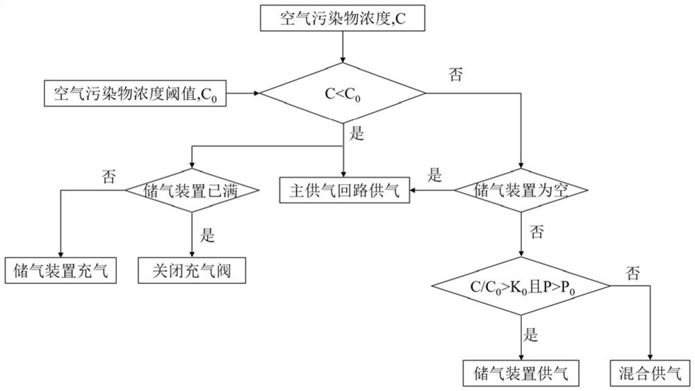
[0005] In order to solve the problem that the filter efficiency and life of the fuel cell air supply system are reduced in the harsh air environment, and some harmful gases are difficult to filter, the present invention proposes an air supply system and a control method, adding compressed air storage equipment to the air supply system , the corresponding pipeline, when the air quality of the working environment of the fuel cell system meets the requirements, store compressed air, when the air quality is poor, switch the system intake mode according to the concentration of pollutants and the state of the gas storage device, and use a separate gas cylinder to supply air Or mixed air supply mode, under the condition of ensuring that the working requirements of the fuel cell system are met, it can reduce the harm of air pollutants for fuel cell equipment working in harsh environments, optimize the quality of cathode intake air, and prolong the work of the filtration system and membrane electrodes life

Method used


Image

  • Fuel cell air supply system and control method
  • Fuel cell air supply system and control method

Examples


Embodiment Construction

[0029] Embodiments of the present application are described in detail below, examples of which are shown in the drawings, wherein the same or similar reference numerals denote the same or similar elements or elements having the same or similar functions throughout. The embodiments described below by referring to the figures are exemplary, and are only for explaining the present application, and should not be construed as limiting the present application. On the contrary, the embodiments of the present application include all changes, modifications and equivalents falling within the spirit and scope of the appended claims.

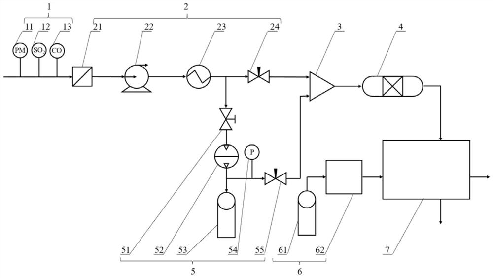
[0030] figure 1 It is a structural schematic diagram of a fuel cell air supply system proposed by an embodiment of the present application.

[0031] see figure 1 and figure 2 , a fuel cell air supply system, including a main air supply circuit 2, an auxiliary air supply pipeline 5, a mixer 3 and a fuel cell stack 7.

[0032] The main air supply circuit...


PUM


Abstract

The invention provides a fuel cell air supply system which comprises a main air supply loop, an auxiliary air supply pipeline, a mixer and a fuel cell stack, a filter and a first regulating valve are sequentially arranged on the main air supply loop from the air inlet end to the air outlet end, and the auxiliary air supply pipeline is connected with the main air supply loop. The air inlet end of the auxiliary air supply pipeline is located between the filter and the first adjusting valve, an electromagnetic valve, an air storage device and a second adjusting valve are sequentially arranged on the auxiliary air supply pipeline from the air inlet end to the air outlet end, and the mixer is connected with the air outlet end of the main air supply loop and the air outlet end of the auxiliary air supply pipeline. And the fuel cell stack is connected with the mixer. The auxiliary air supply pipeline is additionally arranged, the air supply mode is switched according to the real-time air pollutant concentration, the quality of air entering the electric pile when the fuel cell system works in a high pollutant concentration environment is optimized, and the service life of the electric pile and the service life of the air supply system are prolonged.

Description

technical field [0001] The present application relates to the technical field of fuel cells, in particular to a fuel cell air supply system and a control method. Background technique [0002] In the fuel cell system, air with a certain flow rate and pressure is introduced into the cathode to electrochemically react with the hydrogen in the anode to generate electricity. Particles such as dust in the air may block the gas diffusion layer and flow channels. Carbon monoxide, sulfur dioxide, nitrogen oxides and other components in the air will affect the efficiency and life of the catalyst. The fuel cell cathode gas supply system needs to filter the air entering the stack And impurity removal, control pressure and flow to meet the needs of the stack. When the fuel cell system works in an environment with a high concentration of particulate matter and impurity gases, the service life and filtering effect of the filter system will be affected, and the service life of the fuel cel...

Claims


Application Information

Patent Timeline
IPC IPC(8): H01M8/04089H01M8/04082H01M8/04955
CPCH01M8/04089H01M8/04201H01M8/04955Y02E60/50
Inventor 许强王海军刘少权任道远张亦凡朱伟沈泽南
Owner CHINA COAL RES INST
Learn More