Device and method for verifying aircraft engine nacelle pressure relief system

An aircraft engine and nacelle technology, which is applied in the field of devices for verifying the nacelle pressure relief system of an aircraft engine, can solve the problem that the pressure relief performance of the nacelle pressure relief system cannot meet the requirements, the working pressure and temperature of the aeroengine are low, and the nacelle pressure relief To avoid problems such as the increase of system emissions, to avoid distortion of experimental data, improve reliability, and stabilize the test environment

Active Publication Date: 2022-05-13
JINCHENG NANJING ELECTROMECHANICAL HYDRAULIC PRESSURE ENG RES CENT AVIATION IND OF CHINA
View PDF5 Cites 0 Cited by
  • Summary
  • Abstract
  • Description
  • Claims
  • Application Information

AI Technical Summary

Problems solved by technology

The working pressure and temperature of early aero-engines were relatively low, so the design of the nacelle pressure relief system was relatively simple and did not have a significant impact on the performance of the aero-engine
However, with the development of aero-engines towards high bypass ratio and high pressurization ratio, this will lead to a large increase in the discharge of the nacelle pressure relief system, so higher requirements are put forward for the design of the nacelle pressure relief system. However, the pressure relief performance of the early designed nacelle pressure relief system can no longer meet the requirements

Method used


Image

  • Device and method for verifying aircraft engine nacelle pressure relief system
  • Device and method for verifying aircraft engine nacelle pressure relief system
  • Device and method for verifying aircraft engine nacelle pressure relief system

Examples


Embodiment 1

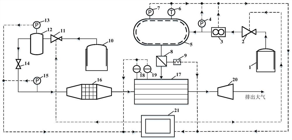
[0053] Such as figure 1 as shown, figure 1 It is a schematic diagram of the experimental bench for testing the pressure relief performance of the aircraft engine nacelle pressure relief system of the present invention, including a pipeline leakage subsystem, a pressure relief door discharge subsystem, a flight environment simulation subsystem and a measurement and control subsystem; the measurement and control subsystem controls The operation of pipeline leakage subsystem, pressure relief door discharge subsystem, and flight environment simulation subsystem. The pipeline leakage subsystem is used to simulate the leakage of the high-pressure bleed air pipeline inside the nacelle. The pressure relief door discharge subsystem is used for the pressure relief process of the nacelle pressure relief system and to obtain the pressure change inside the nacelle. The flight environment simulation subsystem is used to simulate the flight environment at the flight altitude and Mach numbe...

Embodiment 2

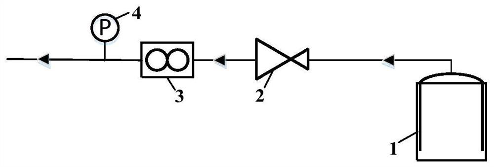
[0061] Such as figure 2 as shown, figure 2 It is the pipeline leakage subsystem of the present invention, which is used to simulate the leakage of the high-pressure bleed air pipeline inside the nacelle, wherein the first gas source 1, the first pressure reducing valve 2 connected in sequence with the first gas source 1, the mass flow rate Meter 3, the first pressure sensor 4 can produce leakage gas with stable pressure and flow rate;

Embodiment 3

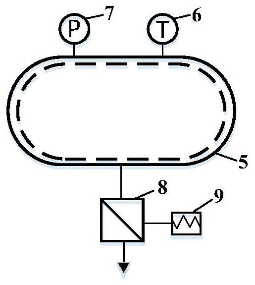
[0063] Such as image 3 as shown, image 3 It is the discharge subsystem of the pressure relief door of the present invention, which is used for the pressure relief process of the nacelle pressure relief system and obtains the pressure change inside the nacelle. When the system is running, the outlet of the nacelle 5 is connected with the pressure relief door 8, and the first temperature The probe of the sensor 6 is arranged in the nacelle 5 for sensing the gas temperature in the nacelle 5; the probe of the second pressure sensor 7 is arranged in the nacelle 5 for sensing the gas pressure in the nacelle 5; attitude The sensor 9 is arranged on the surface of the pressure relief door 8, and is used to sense the posture change of the pressure relief door 8;


PUM


Abstract

The invention discloses a device and a method for verifying a pressure relief system of an aircraft engine nacelle, and belongs to the technical field of safety and reliability of aero-engines, an experimental platform comprises a pipeline leakage subsystem, a pressure relief door discharge subsystem, a flight environment simulation subsystem and a measurement and control subsystem, the experiment table can simulate and experiment the pressure relief performance of the nacelle pressure relief system under different flight environments and different pressure relief door structure parameters, realizes automatic acquisition and storage of each parameter, automatically controls and adjusts each component through the controller, and is simple to build, high in test precision, convenient and safe to operate and high in practicability. The method is suitable for researching main factors and mechanisms which influence the flow characteristics of the pressure relief device of the nacelle pressure relief system and influence the pressure change in the nacelle, and the experimental result can provide a design basis for the technical development of improving the pressure relief performance of the engine nacelle pressure relief system.

Description

technical field [0001] The invention belongs to the technical field of aero-engine safety and reliability, and relates to a device and a method for verifying an aircraft engine nacelle pressure relief system. Background technique [0002] Aeroengines are known as the jewel in the crown of modern industry. While pursuing high efficiency and economy, it is particularly important to be safe and reliable under working conditions. Since there is a high-pressure bleed air pipeline inside the aero-engine nacelle, when the high-pressure bleed air pipeline leaks or bursts, the pressure inside the nacelle will rise rapidly, endangering the safety of the nacelle structure, and even causing engine failure. The pressure system is to ensure that the internal pressure of the nacelle will not cause structural failure after the pipeline ruptures, and it is one of the important guarantees to ensure the normal and safe operation of the engine. [0003] Studies have shown that when a leak occu...

Claims


Application Information

Patent Timeline
Patent Type & Authority Applications(China)
IPC IPC(8): G01M15/14G01M15/02
CPCG01M15/14G01M15/02
Inventor 王晨臣周宇陈昂徐三树
Owner JINCHENG NANJING ELECTROMECHANICAL HYDRAULIC PRESSURE ENG RES CENT AVIATION IND OF CHINA
Why Eureka
Try Eureka