Sound field reconstruction method based on planar array scanning

A technology of sound field reconstruction and plane array, which is used in the measurement of ultrasonic/sonic/infrasonic waves, instruments, complex mathematical operations, etc. It can solve problems such as difficult to meet test conditions, difficult engineering implementation, and severe test conditions, and achieve fast calculation speed. , the effect of a small number of acoustic sensors and a low measurement cost

Active Publication Date: 2022-05-13
NAVAL UNIV OF ENG PLA
View PDF7 Cites 0 Cited by
  • Summary
  • Abstract
  • Description
  • Claims
  • Application Information

AI Technical Summary

Problems solved by technology

The traditional near-field acoustic holography method has excellent performance in the field of noise source identification for small equipment, but for large underwater vehicles, the test conditions are relatively strict, and it is necessary to meet the measurement area not smaller than the sound source surface during the sound field measurement process. size, it often requires a large number of acoustic sensors to form an array to test the sound field, resulting in huge testing costs and difficult engineering implementation
[0004] Through the above analysis, the existing problems and defects of the existing technology are: the traditional near-field acoustic holography method requires the measurement area to be no smaller than the size of the sound source surface. When testing large underwater vehicles, the test conditions may be difficult to meet due to the high cost.

Method used


Image

  • Sound field reconstruction method based on planar array scanning
  • Sound field reconstruction method based on planar array scanning
  • Sound field reconstruction method based on planar array scanning

Examples


Embodiment Construction

[0074] In order to make the object, technical solution and advantages of the present invention more clear, the present invention will be further described in detail below in conjunction with the examples. It should be understood that the specific embodiments described here are only used to explain the present invention, not to limit the present invention.

[0075] Aiming at the problems existing in the prior art, the present invention provides a sound field reconstruction method, which will be described in detail below in conjunction with the accompanying drawings.

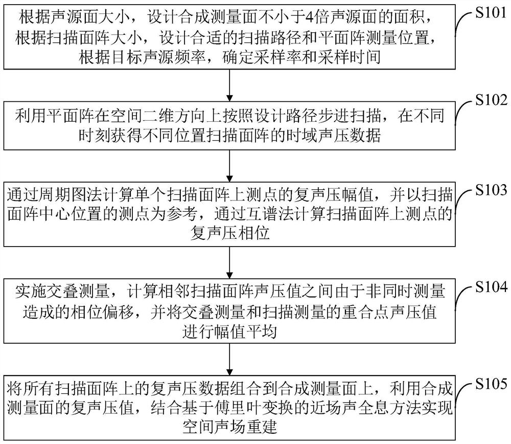
[0076] Such as figure 1 As shown, the sound field reconstruction method provided by the embodiment of the present invention includes the following steps:

[0077] S101, according to the size of the sound source surface, design a synthetic measurement surface not less than 4 times the area of ​​the sound source surface, design a suitable scanning path and planar array measurement position according to the size of ...


PUM


Abstract

The invention belongs to the technical field of mechanical structure sound radiation signal processing, and discloses a sound field reconstruction method based on planar array scanning, which comprises the following steps of: performing stepping scanning in a spatial two-dimensional direction by using a small planar array to obtain sound pressure data of scanning planar arrays at different positions; overlapping measurement is carried out in adjacent areas of the scanning area arrays, and phase deviation caused by non-simultaneous measurement between sound pressure values of the adjacent scanning area arrays is calculated; and by averaging the sound pressure amplitudes at the overlapping positions, the complex sound pressure data on all the scanning area arrays are combined to the synthetic measurement surface. And the sound pressure value of the synthetic measurement surface is combined with a near-field acoustical holography method based on Fourier transform to realize reconstruction of a space sound field. According to the method, the sound field measurement and reconstruction in a larger range are completed by using fewer measuring points, the number of required acoustic sensors is small, the measurement cost is low, the sound field reconstruction precision is high, the calculation speed is high, the window effect problem in a traditional sound field reconstruction method is effectively avoided, and the size modulation of a synthetic measurement surface is realized.

Description

technical field [0001] The invention belongs to the technical field of acoustic radiation signal processing of mechanical structures, and relates to a sound field reconstruction method based on plane array scanning. Background technique [0002] Nearfield Acoustic Holography (Nearfield Acoustic Holography, NAH) is a high-resolution sound field reconstruction method, which uses an acoustic sensor array to collect sound field information near the sound source, and then calculates the sound pressure and sound intensity in three-dimensional space through a space transformation algorithm. and the vibration velocity of the particle, and the sound pressure and normal vibration velocity on the sound source surface can also be obtained at the same time, so that the visualization of the sound field and the vibration analysis of the structure can be realized. application. [0003] There are a large number of active mechanical devices inside a large underwater vehicle, which will excit...

Claims


Application Information

Patent Timeline
IPC IPC(8): G01H17/00G06F17/14
CPCG01H17/00G06F17/14
Inventor 陈志敏张旭昕楼京俊卢锦芳
Owner NAVAL UNIV OF ENG PLA
Why Eureka
Try Eureka