


Quick Research
Generate reliable direction feasibility study reports for your R&D in just a few steps.

Technical Q&A
Discover and master advanced knowledge NOW. Basics, ideas, possibilities, all at once.

Find Solutions
As an expert in R&D theories, this can generate solutions to your technical problems instantly.

Evaluate Feasibility
Analyze your overall solution with one click, know your potential R&D risks in advance.

Monitor Landscape
Get weekly tech updates, stay abreast of the latest tech innovations and key insights.
Electro-hydraulic integrated switch and application thereof
An electro-hydraulic and switch technology, which is applied in the direction of mining fluid, drill pipe, casing, etc., can solve the problems of high power and difficult switch adjustment, and achieve the effect of high power and difficult switch adjustment
- Summary
- Abstract
- Description
- Claims
- Application Information
AI Technical Summary
Problems solved by technology
Method used
Image

Examples
Embodiment 1
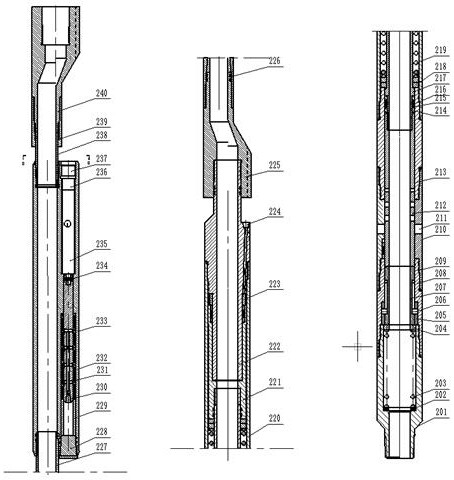
[0040] like figure 1 As shown, the electro-hydraulic integrated switch includes a lower joint 201, a spring seat 202, a lower spring 203, a bearing 204, a rail fixing sleeve 205, a rail pin 206, a rail sleeve 207, a lower connecting sleeve 208, a rubber ring 1 209, and an intermediate connecting sleeve 210, oil production outer hole 211, sliding sleeve 212, upper connecting sleeve 213, copper ring 214, polytetrafluoroethylene 215, rubber ring 2 216, inner connecting rod 217, washer 218, upper spring 219, outer jacket 220, piston 221, upper Connector 222, gear ring 223, hydraulic control connector 224, variable center sleeve 1 225, quick connector 1 226, connecting nipple 1 227, large screw plug 228, support sleeve 229, small screw plug 230, sealing system 231, mandrel 232 , main body 233, pin 234, motor 235, control circuit board 236, cable connector 237, connecting nipple 2 238, quick connector 2 239, variable center sleeve 2 240, the lower joint 201 is provided with a step i...
Embodiment 2
[0055] like Figure 7 As shown, the 7in cased well layered sand control layered oil production string includes a plug 1, an electro-hydraulic integrated switch 2, a sand filter pipe 3, a through-type sealing plug 4, a sand control layered packer 5, and a sand control sleeve Pipe 6, oil production pipe 7, positioner 8, armored cable 9, hydraulic control pipeline 10, electric pump unit 11, electric pump strengthening device 12, power cable 13;
[0056] The sand control casing 6, the sand control layered packer 5 and the sand filter pipe 3 form a sand control string on the outer wall, the plug 1, the electro-hydraulic integrated switch 2, the through-type sealing plug 4, the hydraulic control pipeline 10, Armored cable 9, oil production tubing 7, positioner 8, electric pump unit 11, electric pump strengthening device 12, and power cable 13 form the internal oil production string. For each oil layer, the sand filter pipe 3 is aligned with each oil layer, the sand control casing 6...
Embodiment 3
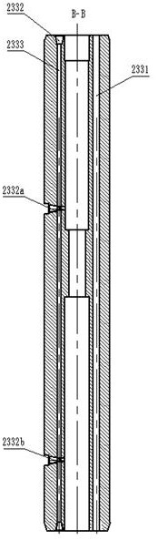
[0059] The method of using the 7in cased well layered sand control layered oil production string described in Example 2 to perform oil recovery: send instructions through the ground control center and supply power to the motor 235 to push the mandrel 232 to move, and when it is necessary to provide the electro-hydraulic integration of the control layer When the switch is pressed, push the mandrel to Figure 5The first position in the pressure position is the pressure position. At this time, the pressure joints 2334 and 2334a are unblocked. Then, according to the size of the dispensing volume, the pressure is controlled through the hydraulic control pipeline. When a certain pressure is reached, the upper spring 219 and the lower spring 203 are compressed to continue to improve pressure, the track sleeve 207 moves on the track fixed sleeve 205, thereby driving the sliding sleeve 212 to move up and down. Since the sliding sleeve is provided with multiple injection holes of differe...
PUM
 Abstract
Description
Claims
Application Information
 - R&D Engineer
- R&D Manager
- IP Professional
- Industry Leading Data Capabilities
- Powerful AI technology
- Patent DNA Extraction
Browse by: Latest US Patents, China's latest patents, Technical Efficacy Thesaurus, Application Domain, Technology Topic, Popular Technical Reports.
© 2024 PatSnap. All rights reserved.Legal|Privacy policy|Modern Slavery Act Transparency Statement|Sitemap|About US| Contact US: help@patsnap.com