
Oxygen generator, gas storage tank of oxygen generator and forming die and forming method of gas storage tank

A technology for forming molds and gas storage tanks, which is applied to chemical instruments and methods, fixed-capacity gas storage tanks, and other household appliances. The effect of improving heat dissipation efficiency and improving pass rate

Pending Publication Date: 2022-05-13
NANJING YINUOJI MEDICAL TECH CO LTD
View PDF1 Cites 0 Cited by
  • Summary
  • Abstract
  • Description
  • Claims
  • Application Information

AI Technical Summary

Problems solved by technology

[0004] There is only one gas storage chamber in the gas storage tank in the prior art, and the volume of the gas storage chamber is relatively large, and it is impossible to accurately identify the gas in the gas storage chamber. Therefore, it is necessary to design a gas storage tank that meets the requirements, and at the same time , also put forward higher requirements for the forming mold of the gas storage tank

Method used


Image

  • Oxygen generator, gas storage tank of oxygen generator and forming die and forming method of gas storage tank
  • Oxygen generator, gas storage tank of oxygen generator and forming die and forming method of gas storage tank
  • Oxygen generator, gas storage tank of oxygen generator and forming die and forming method of gas storage tank

Examples


Embodiment 1

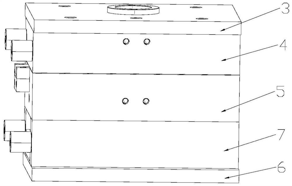
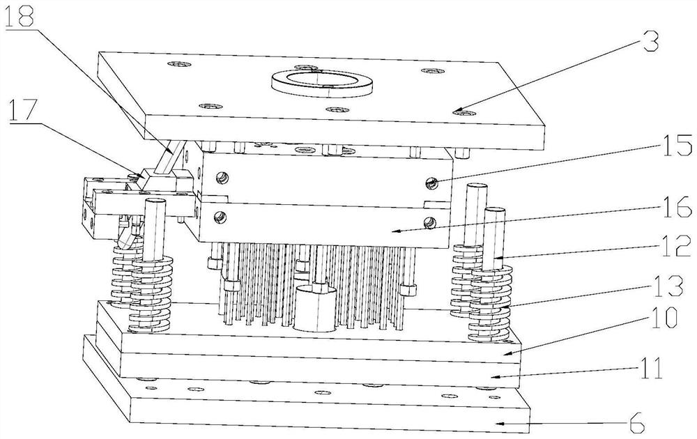
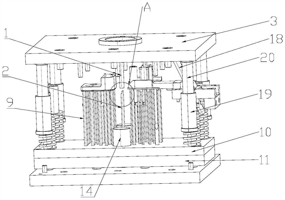
[0065] Such as Figures 1 to 5 Shown, a kind of air storage tank forming mold comprises at least two cavities, and the cavity is arranged in the middle of the forming mold; the injection channel 1, the injection channel 1 is arranged in the upper part of the forming mold, and its upper port extends to the forming mold The upper end surface of the upper end, the lower end of which is connected to the cavity; the pulling rod 2, the upper end of the pulling rod 2 blocks the lower port of the injection channel 1; the first jacking part, the lower part of the cavity is provided with The corresponding first jacking member. The injection slurry is injected into the cavity from the injection channel 1 to form the finished gas storage tank. The finished product is released from the cavity through the first jacking part, and the slurry forms condensate in the injection channel 1, which affects the next grouting. After the condensate condenses, it is connected to the upper end of the pu...

Embodiment 2

[0076] Such as Figures 6 to 7 As shown, the gas storage tank of the oxygen generator includes an upper cover 21, which is molded through a cavity in the above-mentioned forming mold; a tank body 22, which is formed by another type of the above-mentioned forming mold. The cavity is formed; the upper cover 21 is ultrasonically welded on the upper end surface of the tank body 22 to form a sealed first cavity. The first air inlet 25 is arranged on one side of the upper cover 21, which communicates with the first cavity; the first air outlet 26 and the first air inlet 25 are arranged on the same side of the upper cover 21, which communicated with the first cavity. On the upper cover 21 of the second cavity 24; the second air inlet 27 is arranged between the first air inlet 25 and the first air outlet 26, and it communicates with the second cavity 24; the second air outlet 28 is arranged between the first air inlet 27 and the first air outlet 26, which communicates with the secon...

Embodiment 3

[0082] A method for forming an oxygen generator gas storage tank, comprising the following steps:

[0083] S1. Clamp the upper template 3, the upper mold base 4, the lower template 5 and the lower mold base 6;

[0084] S2. Pass coolant into the cooling channel;

[0085] S3. inject the slurry into the cavity through the injection channel 1, and form the gas storage tank product;

[0086] S4. Ejecting the product through the first jacking member and the first jacking member.


PUM


Abstract

The invention relates to the technical field of oxygen generators, in particular to an oxygen generator, a gas storage tank of the oxygen generator and a forming die and method of the gas storage tank, the oxygen generator comprises at least two cavities, and the cavities are formed in the middle of the forming die; the injection molding channel is arranged at the upper part of the forming mold, the upper port of the injection molding channel extends to the upper end surface of the forming mold, and the lower end of the injection molding channel is communicated with the cavity; the upper end of the material pulling rod blocks the lower end opening of the injection molding channel; and the lower part of the cavity is provided with the corresponding first jacking component. The mold of the device can mold two parts of the gas storage tank at a time, so that the molding efficiency is improved.

Description

technical field [0001] The invention relates to the technical field of oxygen generators, in particular to an oxygen generator, an air storage tank thereof, and a molding die and a molding method for the gas storage tank. Background technique [0002] Oxygen concentrator is a kind of machine for producing oxygen. Its principle is to use air separation technology to separate oxygen in the air from other gases, so as to realize a kind of machine for oxygen production. The compressor fills the gas into the molecular sieve group, and after generating oxygen, it directly enters the gas storage tank. When the breathing end needs oxygen, it directly obtains oxygen from the gas storage tank. The oxygen output is relatively general. Therefore, the gas storage tank is a an integral part of the machine. [0003] Chinese patent CN201920448360.6 provides a gas storage tank for a medical oxygen generator, including a sealing cover, a main body of the gas storage tank, a connecting transm...

Claims


Application Information

Patent Timeline
Patent Type & Authority Applications(China)
IPC IPC(8): B29C45/26B29C45/40C01B13/02F17C1/00
CPCB29C45/26B29C45/4005C01B13/0229F17C1/00C01B2210/0028B29C2045/2683B29L2031/7156
Inventor 徐骁
Owner NANJING YINUOJI MEDICAL TECH CO LTD
Learn More