Pole piece die cutting method and system
A pole piece, die-cutting technology, applied in metal processing equipment, welding equipment, manufacturing tools, etc., can solve the problem of high scrap rate, and achieve the effect of improving the yield rate, eliminating defects, and reducing the scrap rate of pole pieces
- Summary
- Abstract
- Description
- Claims
- Application Information
AI Technical Summary
Problems solved by technology
Method used
Image
Examples
Embodiment 1
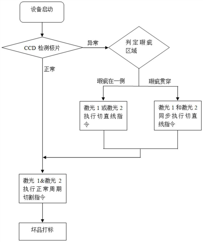
[0074] This embodiment provides a skip-cutting method in which a defect runs through both the first region and the second region of the pole piece.
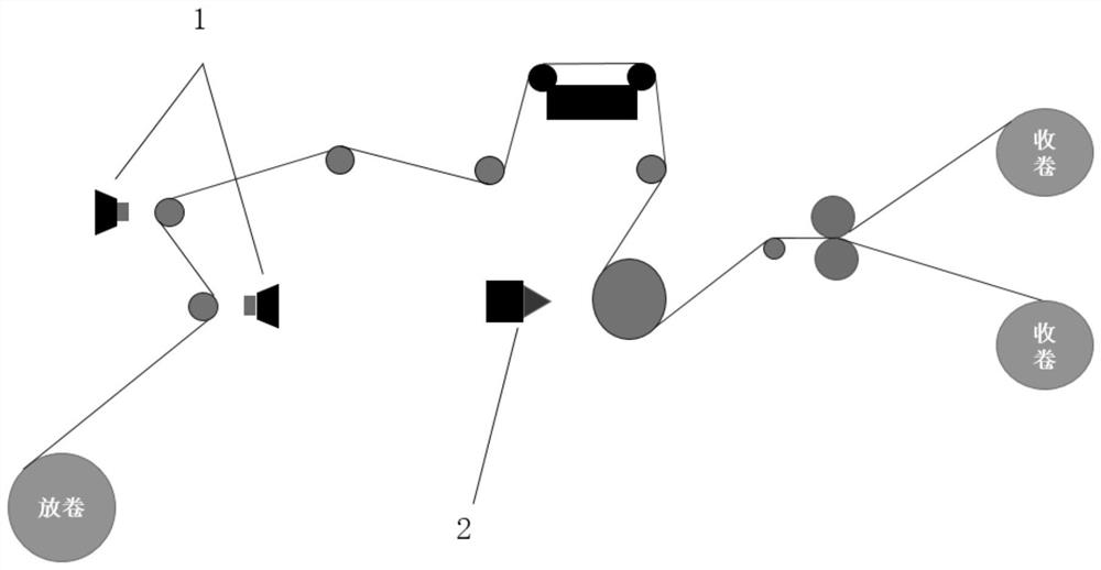
[0075] The CCD is fixed in front of the processing station. Through the distance from the CCD detection station to the laser processing station and the defect coordinates in the pole piece coordinate system, the upper computer can calculate the distance S from the pole piece die-cutting station to the defect position. The belt speed is V. The upper computer outputs a control signal to the laser, so that the laser performs a straight-line cutting action after T=S / V seconds, and adjusts the defect area. like Figure 7 As shown, the cutting path is as follows:
[0076] The upper computer outputs the control signal → the laser executes the normal cutting cycle → (after T seconds) the laser executes the linear cutting command and cuts the fixed length S1 → Mark hole cutting, so the cutting of the current cycle is completed, and the ...
Embodiment 2
[0079] This embodiment provides a jump cut method in which the defect is only in the first area.
[0080] The CCD camera 1 is fixed in front of the processing station. Through the distance from the CCD detection station to the laser processing station and the defect coordinates in the pole piece coordinate system, the host computer can calculate the distance S from the pole piece die-cutting station to the defect position. The speed of the device is V. The upper computer outputs a control signal to the side laser corresponding to the first area, so that the side laser performs a straight line cutting action after T=S / V seconds, and adjusts the defect area. like Figure 8 As shown, the side cutting path is as follows:
[0081] The host computer outputs a control signal to the laser → the laser performs a normal cutting cycle → (after T seconds) the laser in the first area executes a straight line cutting command and cuts a fixed length S1, and the laser in the second area 2 e...
Embodiment 3
[0084] This embodiment provides a defect classification method, the method is as follows:
[0085] When a defect is detected, the type of the defect is determined according to the gray range of the defect, the area of the defect, the diameter of the defect, and / or the width of the defect;
[0086] Make statistics on the types of defects and calculate the proportion of various defects;
[0087] According to the proportion of various defects, output the distribution map of defective products, such as Figure 9 shown.
[0088] More preferably, when the gray scale range of the defect is 90-120, and the area of the defect is >0.5mm 2 , then the type of defect is judged as: metal leakage in the coating film area;
[0089] When the gray scale range of the defect is 90-120, and 0.2mm 2 2 , then it is judged that the type of defect is a scratch in the coating film area;
[0090] When the gray scale range of the defect is 190-220, and the defect area is >0.5mm 2 , then it is j...
PUM
 Abstract
Description
Claims
Application Information
 - R&D Engineer
- R&D Manager
- IP Professional
- Industry Leading Data Capabilities
- Powerful AI technology
- Patent DNA Extraction
Browse by: Latest US Patents, China's latest patents, Technical Efficacy Thesaurus, Application Domain, Technology Topic, Popular Technical Reports.
© 2024 PatSnap. All rights reserved.Legal|Privacy policy|Modern Slavery Act Transparency Statement|Sitemap|About US| Contact US: help@patsnap.com


