


Quick Research
Generate reliable direction feasibility study reports for your R&D in just a few steps.

Technical Q&A
Discover and master advanced knowledge NOW. Basics, ideas, possibilities, all at once.

Find Solutions
As an expert in R&D theories, this can generate solutions to your technical problems instantly.

Evaluate Feasibility
Analyze your overall solution with one click, know your potential R&D risks in advance.

Monitor Landscape
Get weekly tech updates, stay abreast of the latest tech innovations and key insights.
Gas-liquid two-phase power type separated heat pipe device
A separate heat pipe, gas-liquid separator technology, applied in indirect heat exchangers, lighting and heating equipment, etc., can solve problems such as bulky, expensive engineering, and difficult installation.
- Summary
- Abstract
- Description
- Claims
- Application Information
AI Technical Summary
Problems solved by technology
Method used
Image

Examples
Embodiment 1
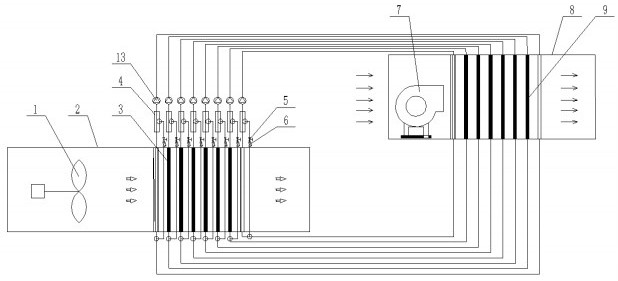
[0030] according to figure 1 As shown, a liquid separation circuit is connected to the heat pipe, and the liquid separation circuit includes a gas-liquid separator a4, and the gas-liquid separator a4 is installed on the gas path between the heat pipe evaporation end 3 and the heat pipe condensation end 9; on the gas-liquid separator a4 There is a pipeline a connected, and the end of the pipeline a is connected to the liquid path between the evaporating end 3 of the heat pipe and the condensing end 9 of the heat pipe; the valve group a5 and the check valve a6 are installed on the pipeline a, and the valve group a5 is located at the check valve Between a6 and gas-liquid separator a4. The pumping device is an air pump 13 installed on the air path of the heat pipe, and the gas-liquid separator a4 is located between the air pump 13 and the evaporation end 3 of the heat pipe.
[0031] Working fluid circulation mode:
[0032] The liquid working medium absorbs heat at the evaporatin...
Embodiment 2
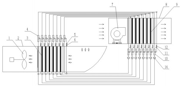
[0034] according to figure 2 As shown, a liquid separation circuit is connected to the heat pipe, and the liquid separation circuit includes a gas-liquid separator a4, and the gas-liquid separator a4 is installed on the gas path between the heat pipe evaporation end 3 and the heat pipe condensation end 9; on the gas-liquid separator a4 There is a pipeline a connected, and the end of the pipeline a is connected to the liquid path between the evaporating end 3 of the heat pipe and the condensing end 9 of the heat pipe; the valve group a5 and the check valve a6 are installed on the pipeline a, and the valve group a5 is located at the check valve Between a6 and gas-liquid separator a4. At the same time, a gas separation circuit is connected to the heat pipe, and the gas separation circuit includes a gas-liquid separator b10, which is installed on the liquid path; a pipeline b is connected to the gas-liquid separator b10, and the end of the pipeline b is connected to the gas On t...
Embodiment 3
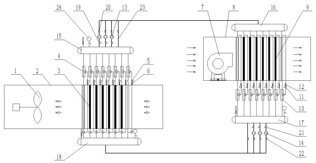
[0038] according to image 3 As shown, a liquid separation circuit is connected to the heat pipe, and the liquid separation circuit includes a gas-liquid separator a4, and the gas-liquid separator a4 is installed on the gas path between the heat pipe evaporation end 3 and the heat pipe condensation end 9; on the gas-liquid separator a4 There is a pipeline a connected, and the end of the pipeline a is connected to the liquid path between the evaporating end 3 of the heat pipe and the condensing end 9 of the heat pipe; the valve group a5 and the check valve a6 are installed on the pipeline a, and the valve group a5 is located at the check valve Between a6 and gas-liquid separator a4. At the same time, a gas separation circuit is connected to the heat pipe, and the gas separation circuit includes a gas-liquid separator b10, which is installed on the liquid path; a pipeline b is connected to the gas-liquid separator b10, and the end of the pipeline b is connected to the gas On th...
PUM
 Abstract
Description
Claims
Application Information
 - R&D Engineer
- R&D Manager
- IP Professional
- Industry Leading Data Capabilities
- Powerful AI technology
- Patent DNA Extraction
Browse by: Latest US Patents, China's latest patents, Technical Efficacy Thesaurus, Application Domain, Technology Topic, Popular Technical Reports.
© 2024 PatSnap. All rights reserved.Legal|Privacy policy|Modern Slavery Act Transparency Statement|Sitemap|About US| Contact US: help@patsnap.com