Permanent magnet motor assembly line winding device
What is Al technical title?
Al technical title is built by PatSnap Al team. It summarizes the technical point description of the patent document.
A technology of winding device and permanent magnet motor, which is used in electromechanical devices, manufacturing motor generators, electrical components, etc., can solve the problems of reducing winding efficiency, no movement adjustment of winding manipulator, and no fast material changing function, etc. The effect of improving winding efficiency
Inactive Publication Date: 2022-05-06
WUXI ASSEMBLE AUTOMATION EQUIP
View PDF0 Cites 0 Cited by
Summary
Abstract
Description
Claims
Application Information
AI Technical Summary
This helps you quickly interpret patents by identifying the three key elements:
Problems solved by technology
Method used
Benefits of technology
Problems solved by technology
[0005] The purpose of the present invention is to solve the problem that the automatic winding machine in the prior art has no quick refueling function. After winding a motor rotor, it is necessary to remove the wound motor rotor, and then install the unwound wire In the process of replacing the motor rotor, the winding cannot be performed, which will reduce the winding efficiency, and the winding manipulator of the automatic winding machine has no movement adjustment function, so it cannot be wound for motor rotors of different diameters , and it is impossible to clamp motor rotors with different diameters, and there is no shortcoming of general function, so a permanent magnet motor assembly line winding device is proposed
Method used
Image
Click on the blue label to locate the original text in one second.
Reading with bidirectional positioning of images and text.
Examples
Embodiment Construction
[0026] The following will clearly and completely describe the technical solutions in the embodiments of the present invention with reference to the accompanying drawings in the embodiments of the present invention. Obviously, the described embodiments are only some, not all, embodiments of the present invention.
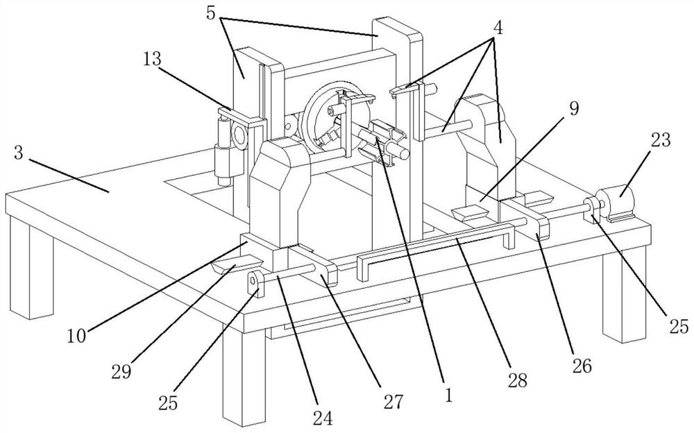
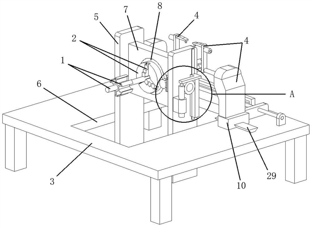
[0027] refer to Figure 1-6 , a permanent magnet motor assembly line winding device, including an automatic winding machine, two motor rotors 1 and two three-grip chucks 2, the automatic winding machine includes a worktable 3 and two winding manipulators 4, and also includes :
[0028] U-shaped frame 5, one side of the worktable 3 is provided with a through hole 6, and the U-shaped frame 5 is fixed on the inner side of the through hole 6;
[0029] Rotating block 7, the rotating block 7 is arranged on the inside of the U-shaped frame 5, and an automatic reciprocating rotating assembly is arranged between the rotating block 7 and the U-shaped frame 5;
[0030] Rotati...
PUM
Abstract
The invention relates to the technical field of motors, in particular to a permanent magnet motor assembly line winding device which comprises an automatic winding machine, two motor rotors and two three-jaw chucks, the automatic winding machine comprises a working table plate and two winding manipulators, the winding device further comprises a U-shaped frame, one side of the working table plate is provided with a through hole, and the U-shaped frame is fixed to the inner side of the through hole; the rotating block is arranged on the inner side of the U-shaped frame, and an automatic reciprocating rotating assembly is arranged between the rotating block and the U-shaped frame; a round hole is formed in one side of the rotating round plate and one side of the rotating block, the rotating round plate can rotate on the inner side of the round hole, and the two three-jaw chucks are fixed to the two sides, away from each other, of the rotating round plate respectively. Through the arrangement of the three-jaw chuck, the U-shaped frame, the through hole, the rotating block, the rotating circular plate, the sliding block A, the sliding block B, the rotating gear, the rotating shaft, the sliding frame, the rack, the mounting base and the hydraulic cylinder, the wire winding device has the universal functions of clamps, rapid material changing, synchronous reverse adjustment and wire winding.
Description
technical field [0001] The invention relates to the technical field of motors, in particular to a winding device for an assembly line of a permanent magnet motor. Background technique [0002] Motor, commonly known as "motor", refers to an electromagnetic device that realizes the conversion or transmission of electric energy according to the law of electromagnetic induction. The principle is: the direction of the force on the conductor is determined by the left-hand rule. This pair of electromagnetic forces forms a torque acting on the armature. This torque is called electromagnetic torque in the rotating electrical machine. The direction of the torque is counterclockwise, trying to make the armature rotate counterclockwise. If this electromagnetic torque can overcome the resistance torque on the armature (such as the resistance torque caused by friction and other load torques), the armature can rotate counterclockwise. [0003] When the permanent magnet motor is manufactu...
Claims
Application Information
Patent Timeline
Application Date:The date an application was filed.
Publication Date:The date a patent or application was officially published.
First Publication Date:The earliest publication date of a patent with the same application number.
Issue Date:Publication date of the patent grant document.
PCT Entry Date:The Entry date of PCT National Phase.
Estimated Expiry Date:The statutory expiry date of a patent right according to the Patent Law, and it is the longest term of protection that the patent right can achieve without the termination of the patent right due to other reasons(Term extension factor has been taken into account ).
Invalid Date:Actual expiry date is based on effective date or publication date of legal transaction data of invalid patent.