Winding core transformer unloading turning frame

A technology for transformers and coiled iron cores, which is applied in the field of coiled iron core transformer unloading and turning frame, which can solve the problems of heavy core weight, inability to meet the unloading work of large coiled iron core transformer cores, and difficulty in the center of gravity of the iron core.

Active Publication Date: 2016-02-24
TAIPINGYANG POWER EQUIP GROUP CHANGZHOU +1
View PDF5 Cites 0 Cited by
  • Summary
  • Abstract
  • Description
  • Claims
  • Application Information

AI Technical Summary

Problems solved by technology

[0002] At present, due to the relatively heavy weight of the iron core used for large-scale wound-core transformers, and the irregular shape of the iron core after winding, it is difficult to find the center of gravity accurately. The material method will not be able to meet the core unloading work of large coiled core transformers. In addition, the annealing method of conventional small coiled core transformers is that the single core is in an upright state, and the weight of large coiled core transformers is relatively heavy. The height is relatively high, and the single-piece iron core in the conventional vertical annealing method may cause undesirable phenomena such as sagging of the upper iron yoke and deformation of the core column during the annealing process under the influence of its own gravity during high-temperature annealing. Core annealing needs to adopt the iron core lying form

Method used


Image

  • Winding core transformer unloading turning frame
  • Winding core transformer unloading turning frame
  • Winding core transformer unloading turning frame

Examples


Embodiment Construction

[0017] In order to make the content of the present invention more clearly understood, the present invention will be further described in detail below based on specific embodiments and in conjunction with the accompanying drawings.

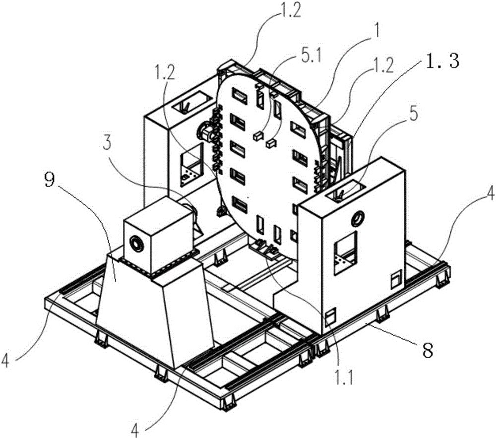
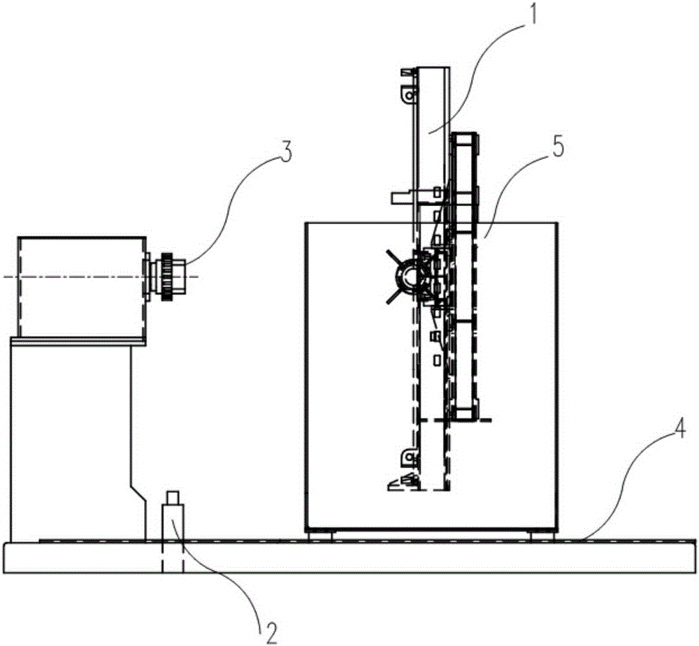
[0018] Such as figure 1 , 2 As shown, a rolling iron core transformer unloading turning frame, which includes iron core support and hoisting jig 1, jacking device 2, iron core core mold expansion mechanism 3, frame 8, turning frame 1.3, unloading turning Support platform 5, rocker turning mechanism and driving device, iron core core mold expansion mechanism 3 is installed on the iron core winding machine 9, and is coaxial with its transmission shaft, turning frame 1.3 is rotatably supported on the unloading turning support platform 5, the rocker arm turning mechanism is arranged between the turning frame 1.3 and the unloading turning support platform 5 so that it drives the turning frame 1.3 to rotate relative to the unloading turning support plat...


PUM


Abstract

The invention discloses a discharging rollover frame for a roll iron core transformer which comprises an iron-core support and lifting clamp, a jacking device, an iron-core centrifugal mold expanding and sleeving mechanism, a frame, an overturn frame, discharging overturn support platforms, a rocker overturn mechanism and a driving device. The iron-core centrifugal mold expanding and sleeving mechanism is mounted on an iron core winding machine and is coaxial to a driving shaft of the iron-core centrifugal mold expanding and sleeving mechanism, the overturn frame is rotatably supported on the discharging overturn support platforms, the rocker overturn mechanism is arranged between the overturn frame and the discharging overturn support platforms so as to drive the overturn frame to rotate relative to the discharging overturn support platforms, the iron-core support and lifting clamp is movably clamped on the overturn frame, the discharging overturn support platforms are slidably arranged on the frame, and the discharging overturn support platforms are driven through the driving device to slide relative to the frame to be close to or far away from the iron core winding machine; the jacking device is mounted on the frame. By the arrangement, the problem that an iron core used for the large-sized roll iron core transformer has difficulty in discharging and overturning is solved, the discharging rollover frame is convenient to operate and safe and reliable; universality for the iron cores different in diameter and window size is achieved, and practical effect is good.

Description

technical field [0001] The invention relates to a rolling iron core transformer unloading turning frame. Background technique [0002] At present, due to the relatively heavy weight of the iron core used for large-scale wound-core transformers, and the irregular shape of the iron core after winding, it is difficult to find the center of gravity accurately. The material method will not be able to meet the core unloading work of large coiled core transformers. In addition, the annealing method of conventional small coiled core transformers is that the single core is in an upright state, and the weight of large coiled core transformers is relatively heavy. The height is relatively high, and the single-piece iron core in the conventional vertical annealing method may cause undesirable phenomena such as sagging of the upper iron yoke and deformation of the core column during the annealing process under the influence of its own gravity during high-temperature annealing. Core anne...

Claims


Application Information

Patent Timeline
Patent Type & Authority Patents(China)
IPC IPC(8): B65H19/30
Inventor 万洪新高仕斌蔡宝鍠韩正庆吴志强周娟钱鹏何祥照吴强陈刚林彬彬
Owner TAIPINGYANG POWER EQUIP GROUP CHANGZHOU
Why Eureka
Try Eureka