
Rotor lamination group for synchronous reluctance motor

A technology of synchronous reluctance motors and rotor laminations, which is applied in the direction of magnetic circuit rotating parts, electromechanical devices, electrical components, etc., can solve problems such as instability, reduce instability, ensure structural uniformity, and increase limit speed Effect

Active Publication Date: 2022-05-06
江苏慧马科技有限公司
View PDF4 Cites 0 Cited by
  • Summary
  • Abstract
  • Description
  • Claims
  • Application Information

AI Technical Summary

Problems solved by technology

[0005] However, for this method, since the rotor laminations have different shapes on the d-axis and q-axis, when the laminations and the shaft are fixedly connected by mutual extrusion, different degrees of deformation will inevitably occur in both directions ; Especially in the direction of the d-axis, a large degree of deformation will occur from the inner diameter to the outer diameter, so that during the rotation of the shaft body and the lamination stack, instability will occur due to the above deformation, which limits the rotational speed promotion

Method used


Image

  • Rotor lamination group for synchronous reluctance motor
  • Rotor lamination group for synchronous reluctance motor
  • Rotor lamination group for synchronous reluctance motor

Examples


Embodiment Construction

[0042] The following will clearly and completely describe the technical solutions in the embodiments of the present invention with reference to the accompanying drawings in the embodiments of the present invention. Obviously, the described embodiments are only some, not all, embodiments of the present invention.

[0043] Unless otherwise defined, all technical and scientific terms used herein have the same meaning as commonly understood by one of ordinary skill in the technical field of the invention. The terms used in the description of the present invention are only for the purpose of describing specific embodiments, and are not intended to limit the present invention. As used herein, the term "and / or" includes any and all combinations of one or more of the associated listed items.

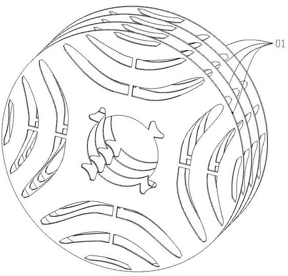
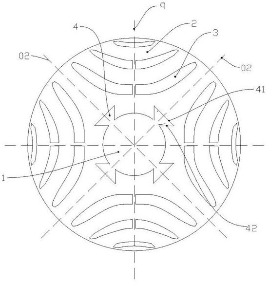
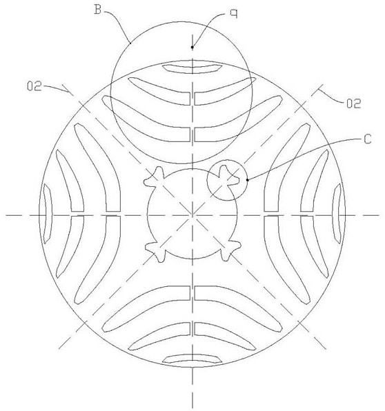
[0044] Such as Figure 1~5 As shown, a rotor lamination group for a synchronous reluctance motor includes a number of stacked rotor laminations 01. The rotor laminations 01 include a cylindrica...


PUM


Abstract

The invention relates to the technical field of synchronous reluctance motors, in particular to a rotor lamination group for a synchronous reluctance motor, a main body of a rotor lamination comprises four deformation buffer parts which are in one-to-one correspondence with half parts of a d axis and are symmetrical about the half parts of the d axis, and the deformation buffer parts are hollow areas obtained by cutting and are arranged at the edge of a through round hole; the opening end is communicated with the through round hole; the edge contour of the deformation buffering part comprises a first side wall and a second side wall, the two second side walls are symmetrically arranged on the two sides of the first side wall, and the edges of the first side wall and the second side walls are in butt joint; the other ends of the two second side walls form opening ends, and the opening ends are in a gathering shape. According to the rotor lamination group provided by the invention, the deformation quantity after the rotor lamination group and the shaft body are mounted can be effectively reduced, the deformation buffer parts are uniformly distributed around the through round hole and are used for accommodating deformation, and the deformation is stopped by the first-stage flow stopping part, so that the deformation is closer to the vicinity of the shaft body, and the instability can be reduced in the rotating process of the shaft body.

Description

technical field [0001] The invention relates to the technical field of synchronous reluctance motors, in particular to a rotor lamination group for synchronous reluctance motors. Background technique [0002] During the processing of the rotor laminations of the synchronous reluctance motor, it is necessary to obtain an arc-shaped strip-shaped magnetic flux guide by punching to guide the magnetic flow, thereby causing high torque efficiency; due to punching The non-magnetic hollow area obtained by the existence of the part is used as the blocking part. [0003] After the rotor laminations are stacked, a lamination group is obtained. The lamination group includes the magnetic blocking direction, that is, the q-axis direction; and the magnetic preferential passing direction, that is, the d-axis direction; the d-axis is continuously composed of laminations from the inner diameter to the outer diameter. A flux guide is formed, while the q-axis is interrupted by a choke. [000...

Claims


Application Information

Patent Timeline
IPC IPC(8): H02K1/22H02K1/28
CPCH02K1/22H02K1/28H02K2213/03
Inventor 赵建军
Owner 江苏慧马科技有限公司
Learn More