
Underwater LED optical beacon and switching method thereof

A technology of LED lamp beads and beacons, applied to illuminated signs, display devices, instruments, etc., can solve the problems of beacon failure, easy attachment by floating objects on the seabed, pressure switch corrosion, etc., to improve reliability and Stability, prolonging the effective working time, and ensuring the effect of waterproof and pressure resistance

Pending Publication Date: 2022-05-06
青岛智慧蓝色海洋工程研究院有限公司
View PDF4 Cites 0 Cited by
  • Summary
  • Abstract
  • Description
  • Claims
  • Application Information

AI Technical Summary

Problems solved by technology

However, at present, the water entry and exit detection devices of underwater LED optical beacons are mostly composed of mechanical pressure switches, and working on the seabed for a long time will cause the pressure switch to suffer from severe seawater corrosion, and it is easy to be attached by floating objects on the seabed, and there is a certain risk of failure. , which in turn affects the smooth implementation of the entire low-power standby process, leading to premature exhaustion of the power supply, resulting in the failure of the entire beacon
On the other hand, the existence of the mechanical pressure switch restricts the diving depth of the whole beacon, and it is difficult to reach the diving depth of the full sea depth (11,000 meters), which limits underwater scientific research activities.

Method used


Image

  • Underwater LED optical beacon and switching method thereof
  • Underwater LED optical beacon and switching method thereof
  • Underwater LED optical beacon and switching method thereof

Examples


Embodiment 1

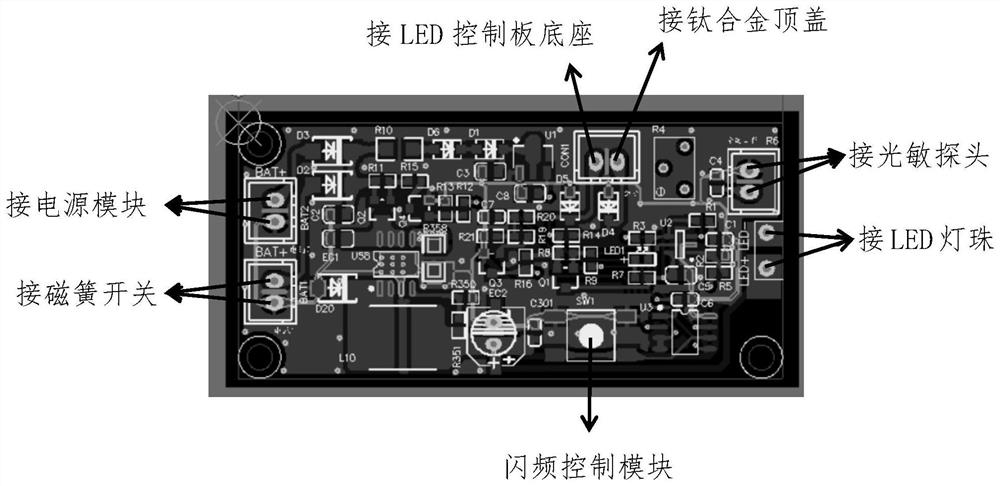
[0035] Example 1, such as figure 1 As shown in -4, this embodiment discloses an underwater LED optical beacon, including a power supply compartment cover 8, a power supply compartment 7, an LED control board protective cover 5, an LED control board base 3, and a plexiglass that are sequentially connected together by threads. The lampshade 2 and the titanium alloy top cover 1, the power supply module 6 is installed in the power supply compartment, the LED control board 4 is installed on the base of the LED control board, the power supply port of the LED control board is electrically connected with the power module, and the switch support is installed on the LED control board. The switch branch circuit includes a magnetic reed switch, a solid-state water sensor and a photosensitive sensor connected in series. The two open-circuit ends of the solid-state water sensor are electrically connected to the titanium alloy top cover and the LED control board base through wires, and the ph...


PUM


Abstract

The underwater LED optical beacon comprises a power supply bin cover, a power supply bin, an LED control panel protection cover, an LED control panel base, an organic glass lampshade and a titanium alloy top cover which are sequentially connected together through threads, a power supply module is installed in the power supply bin, an LED control panel is installed on the LED control panel base, a power supply port of the LED control panel is electrically connected with the power supply module, and a power supply port of the organic glass lampshade is electrically connected with the titanium alloy top cover. A switch branch is installed on the LED control panel and comprises a magnetic reed switch, a solid water sensor and a photosensitive sensor which are connected in series. According to the underwater LED optical beacon, a fully-closed structural design is adopted, all mechanical action structures are abandoned, the problems that an existing underwater LED optical beacon cannot be arranged on an underwater platform of a deep sea for a long time, and reliability is poor are solved, the waterproof and pressure-resistant performance of the optical beacon is guaranteed, the reliability and stability of the optical beacon are improved, and the underwater LED optical beacon has the advantages of being large in diving depth, simple in structure and firm.

Description

technical field [0001] The invention belongs to the field of devices for indicating the water outlet position of underwater equipment, in particular to an underwater LED light beacon capable of indicating the water outlet position of an ocean underwater platform at night and a switching method thereof. Background technique [0002] In the field of marine environmental monitoring, underwater acoustic submersible buoys are the most common platforms for obtaining marine environmental monitoring data. As unattended observation equipment that can be deployed continuously and for a long time underwater, various types of underwater monitoring platforms such as deep sea acoustic submersible buoys, underwater workstations, submarine seismometers, and autonomous underwater vehicles play an important role in marine environmental monitoring. increasingly important role. Considering that the marine environment monitoring system is often deployed underwater at a certain depth, the system...

Claims


Application Information

Patent Timeline
Patent Type & Authority Applications(China)
IPC IPC(8): G09F13/22G09F13/00
CPCG09F13/22G09F13/005G09F2013/222
Inventor 王帅于照成孙冠龙
Owner 青岛智慧蓝色海洋工程研究院有限公司
Learn More