Multi-line laser sensing closed layout structure, scanning splicing method and gluing scanning method

A multi-line laser, layout structure technology, applied in the direction of using optical devices, instruments, measuring devices, etc., can solve the problems of high degree of freedom of equipment, spatial interference, complex programming, etc., to achieve the effect of convenient implementation

Pending Publication Date: 2022-05-06
重庆固高科技长江研究院有限公司
View PDF0 Cites 3 Cited by
  • Summary
  • Abstract
  • Description
  • Claims
  • Application Information

AI Technical Summary

Problems solved by technology

[0011] In view of the problems existing in the above-mentioned prior art that the attitude of the moving mechanism needs to be adjusted to meet the requirements of high degree of freedom of equipment derived from line laser coverage, complex programming, space interference, and inability to balance attitude, the technical problem solved by the present invention is to provide a multi- The layout method of the closed contour detection area composed of two laser scanning lines, the local area to be measured is placed in the closed contour to complete the scanning process, which solves the problem of adjusting the posture of the mobile mechanism at any time. Closed layout structure of multi-line laser sensing, scanning splicing Method and glue scanning method

Method used


Image

  • Multi-line laser sensing closed layout structure, scanning splicing method and gluing scanning method
  • Multi-line laser sensing closed layout structure, scanning splicing method and gluing scanning method
  • Multi-line laser sensing closed layout structure, scanning splicing method and gluing scanning method

Examples


Embodiment Construction

[0047] The present invention will be described in further detail below in conjunction with accompanying drawing:

[0048] Figure 4 , Figure 5 A glue-scanning embodiment of the invention using a six-axis industrial robot is shown.

[0049] see Figure 4 As shown, the gluing scanning method comprises the following steps:

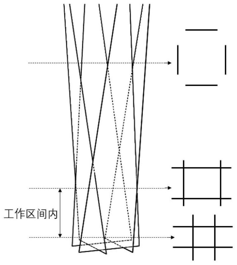
[0050] ⑴ Make the mounting parts, and install the four calibrated line laser sensors evenly to form a closed quadrilateral;

[0051] ⑵Install the mounting parts to the end of the robot, complete the hand-eye matrix calibration of each line laser and the end of the robot, use the standard sphere calibration method, move the robot end posture respectively, move the laser line to the standard sphere, and take 20 poses for each sensor , record the sensing data and robot attitude data, and calculate simultaneously to obtain the sensing hand-eye matrix T n ;

[0052] ⑶ Along the trajectory of the glue road, the end of the translation is programmed to write t...


PUM


Abstract

The invention relates to a multi-line laser sensing closed layout structure, a scanning splicing method and a gluing scanning method. The layout structure is composed of a closed polygon which is formed by projecting a plurality of laser rays within a working distance by one laser for integral projection or a plurality of lasers for respective projection; each laser ray is monitored and measured by an independent receiver or camera, and the receiver only calculates distance information of the corresponding laser ray; the middle area of the polygon is a monitoring target area; during operation, the middle area is fixedly wrapped with an object to be detected; within the working distance, the horizontal projection of the laser line still needs to keep a closed polygonal graph; the number and the projection angle of the laser rays are determined by the shape and the edge included angle of a detected object; when the to-be-detected object is located in the closed contour, no matter the multi-line laser group moves from any direction, the posture of the multi-line laser group does not need to be changed, and at least one receiver scans the to-be-detected object.

Description

technical field [0001] The invention belongs to the technical field of industrial detection, and in particular relates to a closed layout structure of multi-line laser sensing, a scanning splicing method and a gluing scanning method. Background technique [0002] The current industrial detection technology means, commonly used scanning detection means: install a line laser sensor at the end of the moving mechanism, and move through the mechanism to complete the scanning process of the target workpiece. Mobile mechanisms include industrial robots, multi-axis linear modules and other multi-degree-of-freedom mechanisms. [0003] However, for processes that require simultaneous processing of the object to be measured during real-time scanning, such as gluing, welding, additive manufacturing, and subtractive manufacturing, the line laser scanning line must continue to cover the processing part. For such applications, the following schemes are often used if the workpiece consiste...

Claims


Application Information

Patent Timeline
Patent Type & Authority Applications(China)
IPC IPC(8): G01B11/245B25J11/00B25J19/02
CPCG01B11/245B25J19/022B25J19/023B25J11/00
Inventor 陈鹏飞叶云波蒲江王聪毅吴迪
Owner 重庆固高科技长江研究院有限公司
Why Eureka
Try Eureka