Telescopic steel bar cloth hanging trolley

A telescopic and cloth trolley technology, which is applied in shaft equipment, shaft lining, mining equipment, etc., can solve the problems of increased construction safety risks, large arched gantry, and poor road passability, so as to reduce the difficulty of transition , reduce construction costs, and improve passability

Pending Publication Date: 2022-05-06
洛阳中天建工机械有限公司
View PDF0 Cites 0 Cited by
  • Summary
  • Abstract
  • Description
  • Claims
  • Application Information

AI Technical Summary

Problems solved by technology

The body length of the reinforced hanging cloth trolley is generally 12 meters. If the primary lining of this length is not reinforced in time by the secondary lining, the safety risk of construction will be increased
[0004] 2. The existing reinforced hanging cloth trolley has an arched portal frame that is similar to the tunnel arch surface. The arched portal frame is huge in size and poor in road passability, making it difficult to transition
[0005] 3. Since the shape of the arch surface of the tunnel is not necessarily the same, the arched portal frame of the existing steel hanging cloth trolley cannot be applied to all tunnel arch surfaces, resulting in poor versatility and indirectly increasing the construction cost

Method used


Image

  • Telescopic steel bar cloth hanging trolley
  • Telescopic steel bar cloth hanging trolley
  • Telescopic steel bar cloth hanging trolley

Examples


Embodiment 1

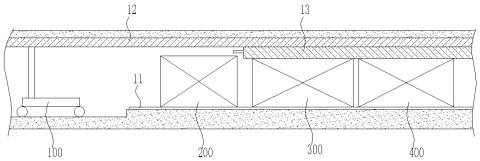
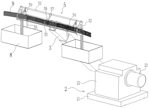
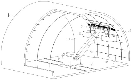
[0033] A telescopic steel hanging cloth trolley, such as Figure 2-3 As shown, a chassis 2 for walking in a tunnel 1 is included. Usually all lay construction track 11 in tunnel 1, so chassis 2 is provided with the traveling wheel driven by traveling motor, and traveling wheel can walk along construction track 11, moves by construction track 11. The chassis 2 is hinged with a telescopic arm 3, and the telescopic arm 3 is connected with a reinforcement hanger 5. Specifically, the chassis 2 is provided with a rotating arm motor 23 with a brake function. After being decelerated by a reducer, the rotating arm motor 23 can make the telescopic arm 3 rotate in the cross section of the arch of the tunnel 1 under the control of the control system. It should be noted that the arm motor 23 can also be replaced by a rotary oil cylinder.

[0034] Such as figure 2 As shown, in this embodiment, the telescopic boom 3 is a three-section telescopic boom 3, and two oil cylinders are arranged...

Embodiment 2

[0040] Different from Example 1, as Figure 5 As shown, the hanging cloth frame 6 and the third rotating cylinder 7 are hinged at both ends of the hinge shaft 51 , and the third rotating cylinder 7 is used to push the hanging cloth frame 6 to rotate relative to the telescopic arm 3 .

[0041] Such as Figure 6 As shown, the cloth hanger 6 includes a frame-shaped frame body 61 on which a reel, a pressing roller 62 , a glue applicator 65 and a movable nail gun 64 are arranged. Specifically, the glue applicator 65 is fixed on one side of the frame body 61, and is used for applying glue to the side of the waterproof cloth. When hanging the cloth, the glue applicator 65 staggers and bonds the sides of the two waterproof cloths together, which can play a role of sealing. It is worth noting that the glue applicator 65 can be replaced by a climbing welding machine. The climbing welding machine does not need to be glued. The climbing welding machine has a roller that can be heated. W...

Embodiment 3

[0048] Different from Embodiment 1, the chassis 2 is composed of a machine base 21 and a cabinet 22 , and the machine base 21 has traveling wheels and can walk along the construction track 11 . The chassis 22 is located above the base and can rotate in a horizontal direction relative to the base 21 . The telescopic arm 3 is rotatably arranged on the casing 22, and the casing 22 is also provided with a rotating arm motor 23, which drives the telescopic arm 3 to rotate after being decelerated by a reducer.

[0049] Such as Figure 8 As shown, arched steel bars 10 are arranged in the receiving groove of the steel bar hanger 5 . After the cabinet 22 is rotated by 90°, the arched steel bar 10 is located in the cross section of the tunnel. At this time, the arched steel bar 10 can be grasped by the rotating arm 57 to assist in laying the arched steel bar 10 . Apparently, such assistance saves time and effort than manually laying the arched steel bar 10 .

[0050] It can be seen ...


PUM


Abstract

A telescopic steel bar cloth hanging trolley comprises a chassis, a telescopic arm is hinged to the chassis, and a steel bar hanging frame and a first rotating cylinder are hinged to the telescopic arm; the telescopic arm can rotate and stretch out and draw back so that the steel bar hanging frame can move in the circumferential direction of the tunnel arch face. The reinforcing steel bar hanging frame is used for assisting an operator to tie the transverse reinforcing steel bars on the arched reinforcing steel bars; the steel bar hanging frame is provided with a containing groove used for containing the transverse steel bars, further provided with a jacking cylinder used for jacking the transverse steel bars in the containing groove one by one and further provided with a rotating arm used for grabbing the transverse steel bars jacked out of the containing groove and turning the transverse steel bars to one side of the arch-shaped steel bars. The pouring length of the secondary lining can be increased, and the safety risk of construction is reduced; according to the invention, the trafficability can be improved, the method can adapt to the construction operation of different tunnel arch surfaces, and the construction cost is reduced; according to the equipment, automatic cloth laying, nailing and gluing of the primary lining are achieved, laying of the secondary lining steel bars is achieved in an auxiliary mode, the mechanical degree is high, efficiency is high, and the construction cost is reduced.

Description

technical field [0001] The invention relates to the field of tunnel engineering equipment, in particular to a telescopic steel hanging cloth trolley. Background technique [0002] The excavation of the tunnel requires the use of special equipment and trolleys. Such as figure 1 As shown, in addition to the excavation equipment, the support of the tunnel requires the use of an arch machine 100 , a reinforcement trolley 200 , a formwork trolley 300 and a maintenance trolley 400 . The strength of the primary lining 12 is not high, and it is not safe, and needs timely reinforcement of the secondary lining 13. The arch erecting machine 100 is located at the front end of the above-mentioned trolley, and is used for arch support to the tunnel initial lining 12 . The reinforcing bar hanging cloth trolley 200 has two functions, and the one is to carry out hanging cloth waterproofing to the first lining 12 arch surfaces, and the 2nd, builds reinforcing bar, prepares for the pouring ...

Claims


Application Information

Patent Timeline
Patent Type & Authority Applications(China)
IPC IPC(8): E21D11/18E21D11/38
CPCE21D11/183E21D11/381
Inventor 韩甘霖韩永锦周金松安波波
Owner 洛阳中天建工机械有限公司
Why Eureka
Try Eureka