
Plunger device

A technology of plunger and main body, which is applied in the field of oil and gas exploitation, can solve problems such as the bulky structure of the wellhead blowout preventer, and achieve the effect of expanding the application depth

Active Publication Date: 2022-05-06
CHINA PETROLEUM & CHEM CORP +1
View PDF14 Cites 0 Cited by
  • Summary
  • Abstract
  • Description
  • Claims
  • Application Information

AI Technical Summary

Problems solved by technology

The traditional plunger device needs to preset the downhole clamping device through steel wire operation, and the clamping device is deeply limited by the steel wire operation capacity. Most of the clamping devices are located above the well deviation of 40°, thus limiting the level of liquid accumulation in the inclined well section and even the horizontal section. Application of Plunger Gas Lift Technology in Well
In addition, in the prior art, it is necessary to install a blowout preventer with a buffer device at the wellhead for buffering the plunger, which makes the structure of the wellhead blowout preventer heavy

Method used


Image

  • Plunger device
  • Plunger device

Examples


Embodiment Construction

[0025] The present invention will be further described below in conjunction with accompanying drawing.

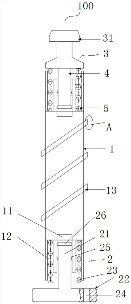
[0026] figure 1 A plunger device 100 according to the invention is shown. Such as figure 1 As shown, the plunger device 100 includes a plunger body 1 and a buffer 2 . Wherein, the plunger body 1 is columnar. The buffer 2 is arranged at the lower end of the plunger body 1 for buffering. During the falling process of the plunger device 100 , the buffer 2 is used to be seated at the clamping position of the oil pipe, so as to achieve the purpose of buffering. By setting the buffer 2, the plunger device 100 can be directly injected into the tubing without pre-installing the downhole retainer. Therefore, the plunger device 100 with the above structure can avoid the use of the downhole retainer and the operation of running in, and thus expand the application depth of the plunger device 100, so that the plunger device 100 is not only suitable for vertical wells with pressure ...


PUM


Abstract

The invention provides a plunger device which comprises a plunger body and a buffer arranged at the lower end of the plunger body, the buffer is used for being located at the clamping position of an oil pipe in the falling process, and the buffer is arranged at the lower end of the plunger device so that the plunger device can be located at the clamping position of the oil pipe in the tripping-in process. Therefore, the situation that devices such as an underground clamping device are tripped into an oil pipe in advance is avoided, the application depth of the plunger device is expanded, and the plunger device is not only suitable for a straight well working under pressure, but also suitable for a highly-deviated well and a horizontal well.

Description

technical field [0001] The invention belongs to the technical field of petroleum and natural gas exploitation, and in particular relates to a plunger device. Background technique [0002] The plunger gas lift process is to use the energy of the gas well itself to discharge the liquid out of the wellbore. The plunger acts as a mechanical interface between the gas and the liquid to prevent the gas from going up and the liquid from falling back, reducing the liquid slippage effect and increasing the intermittent lifting efficiency. The energy of plunger gas lift mainly comes from the reservoir, but when the formation gas energy is insufficient, it can also be supplied by high-pressure gas source from adjacent wells or external high-pressure gas source. These gases push the plunger and the liquid on its upper part from the bottom of the well to the wellhead, remove the liquid at the bottom of the well, increase the production pressure difference, and prolong the production time ...

Claims


Application Information

Patent Timeline
IPC IPC(8): E21B43/12E21B43/00
CPCE21B43/122E21B43/00
Inventor 郭彤楼杜洋林永茂张国东刘通朱江倪杰李莉许剑
Owner CHINA PETROLEUM & CHEM CORP
Learn More