
Continuous while-drilling in-situ test power driving device and construction method

An in-situ testing and power-driven technology, applied in the direction of measurement, drill pipe, drill pipe, etc., can solve the problems of limited test depth and difficulty in meeting the development and utilization of deep underground space, and achieve saving construction procedures, increasing portability, and structural design ingenious effect

Pending Publication Date: 2021-09-17
SHANGHAI GEOTECHN INVESTIGATIONS & DESIGN INST
View PDF0 Cites 0 Cited by
  • Summary
  • Abstract
  • Description
  • Claims
  • Application Information

AI Technical Summary

Problems solved by technology

The testing depth of traditional in-situ testing equipment is limited, and it is difficult to meet the needs of the development and utilization of deep underground space. It is urgent to develop and research a complete set of in-situ testing equipment and construction methods suitable for deep underground space.

Method used


Image

  • Continuous while-drilling in-situ test power driving device and construction method
  • Continuous while-drilling in-situ test power driving device and construction method
  • Continuous while-drilling in-situ test power driving device and construction method

Examples


Embodiment 1

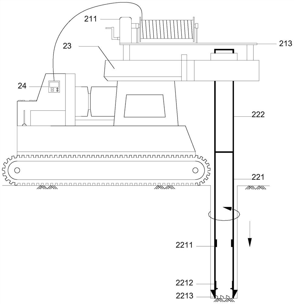
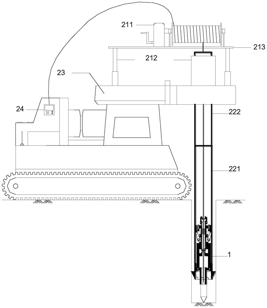
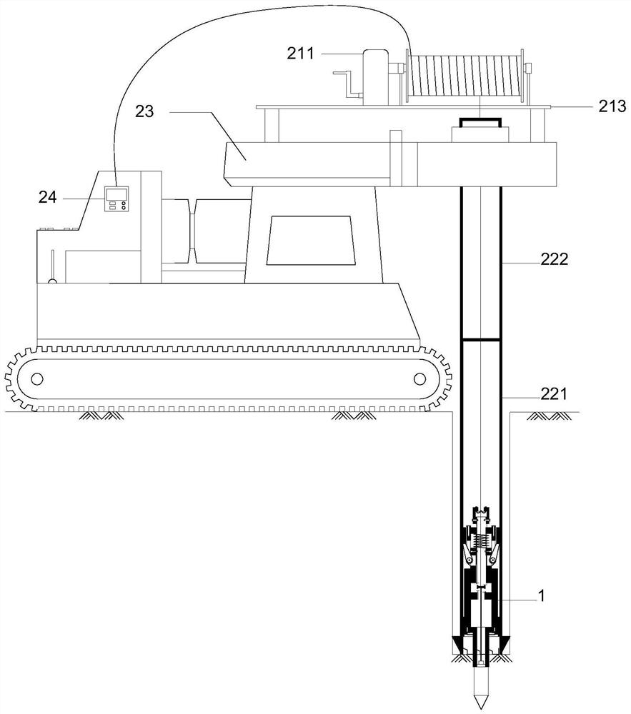
[0039] see Figure 1-11 , a driving device for continuous in-situ testing while drilling, comprising: a drill pipe 22 capable of accommodating and supporting an in-situ test assembly inside; a drilling device 2 with a clamping device for the drill pipe; located on the drilling rig, and capable of An elevating platform that lifts together with the drill pipe clamping device; one end is connected to the in-situ test assembly and can penetrate the cable 14 inside the drill pipe 22; The cable guide device for guiding the cable 14; the claw 132 that is coaxial with the in-situ test assembly and can move axially relative to the in-situ test assembly; the claw 132 can be opened / folded upward; the claw 132 is retracted and reset The jaw retracting device; located above the jaw 132, coaxial with the in-situ test assembly, and a slide block that can move axially relative to the in-situ test assembly; located on the inner wall of the drill pipe 22, the lower end is used to resist Hold t...

Embodiment 2

[0056] This case is the same as the first embodiment except for the cable storage device. For details, see Figure 6-11 .

[0057] The cable storage device in this case includes a slide rail 213 , a pulley 214 , a fuselage hoisting device 215 , and a lifting platform 216 . A pulley 214 is arranged on the slide rail 213, and the pulley 214 can move back and forth along the slide rail 213 to ensure that the cable is in a vertical state during the in-situ test. The pulley 214 is located on the same plane as the fuselage hoisting device 215 and the central axis of the drill pipe; one end of the fuselage hoisting device 215 is connected to the in-situ test assembly, and the other end is connected to the signal receiving device 24, which can be stored manually or electrically. The height of the cable and hoisting device 215 is lower than the top of the drill pipe, and the direction of the force is transformed through the pulley 214; the lifting platform 216 can be lifted at a cert...


PUM


Abstract

The invention relates to a continuous while-drilling in-situ test power driving device. The continuous while-drilling in-situ test power driving device comprises a drill pipe, a lifting platform, a cable, a cable guiding device, a claw, a claw folding device, a sliding block and a positioning grooves; the interior of the drill pipe can contain and support an in-situ test assembly; the lifting platform is arranged on a drilling machine and can ascend and descend together with a drilling pipe clamping device; one end of the cable is connected with the in-situ test assembly, and the cable can penetrate into the drill pipe; the cable guiding device is fixed on the lifting platform and is used for guiding the cable; the claw is coaxial with the in-situ test assembly and can axially move relative to the in-situ test assembly, the claw center of the claw is upward, and the claw can be opened / closed; the claw folding device is used for retracting and resetting the claw; the sliding block is arranged above the claw, is coaxial with the in-situ test assembly and can axially move relative to the in-situ test assembly; and the positioning groove is formed in the inner wall of the drill pipe, and the lower end of the positioning groove is used for abutting against the claw which is opened. When the in-situ test assembly is lowered in place and supported by the drill pipe, the cable in the drill pipe is further loosened, and the sliding block slides downwards under the action of gravity to open the claw and enable the upper portion of the claw to abut against the positioning groove.

Description

technical field [0001] The invention relates to a power driving device and a construction method for continuous in-situ testing while drilling, and belongs to the technical field of in-situ testing. Background technique [0002] Geotechnical survey in-situ test technology can provide reliable geotechnical physical and mechanical property parameters for underground space engineering design. With the development of deep underground space development projects, it is necessary to obtain deeper geotechnical physical and mechanical property parameters through in-situ testing methods. The testing depth of traditional in-situ testing equipment is limited, and it is difficult to meet the needs of the development and utilization of deep underground space. It is urgent to develop and research a complete set of in-situ testing equipment and construction methods suitable for deep underground space. Contents of the invention [0003] The present invention aims at proposing a power drive...

Claims


Application Information

Patent Timeline
Patent Type & Authority Applications(China)
IPC IPC(8): E21B19/10E21B33/04E21B47/12
CPCE21B19/10E21B19/008E21B33/0407E21B47/12
Inventor 金宗川梁振宁曹兴国沈蒙孙莉吴来杰张静陈琛邓海荣李晓飞张晗蔡永生谢飞
Owner SHANGHAI GEOTECHN INVESTIGATIONS & DESIGN INST
Learn More