
Stud welding tool applied to pipeline electric field fingerprint corrosion detection technology

A technology for corrosion detection and electric field fingerprinting, applied in arc welding equipment, manufacturing tools, welding equipment, etc., can solve the problems of accurate welding at the drawn mesh points, inaccurate welding points, affecting the accuracy of detection data, etc. Installation speed and efficiency, the same solder joint burning area, and the effect of standardizing the probe installation procedure

Pending Publication Date: 2022-05-06
CHINA PETROLEUM & CHEM CORP +2
View PDF0 Cites 0 Cited by
  • Summary
  • Abstract
  • Description
  • Claims
  • Application Information

AI Technical Summary

Problems solved by technology

[0002] At present, for the installation of pipeline monitoring device probes based on the electric field fingerprint method, the stud welding technology used is mainly to draw the electrode array dot diagram on the pipeline workpiece, and then the technician holds the stud welding torch to weld the stud electrodes on the dots. , there are many shortcomings in this method of welding electrode arrays by hand-held welding torches, such as imprecise welding points, which cannot ensure that the stud electrodes are accurately welded at the drawn dots; the welding torch height and pressure cannot be kept consistent during welding, causing each stud electrode The depth of welding and the burning area of ​​solder joints are different, resulting in inconsistent studs after welding; the irregular installation of probes affects the accuracy of detection data, thereby affecting the overall performance of the monitoring device; the welding process is time-consuming, laborious and inefficient

Method used


Image

  • Stud welding tool applied to pipeline electric field fingerprint corrosion detection technology
  • Stud welding tool applied to pipeline electric field fingerprint corrosion detection technology
  • Stud welding tool applied to pipeline electric field fingerprint corrosion detection technology

Examples


Embodiment 1

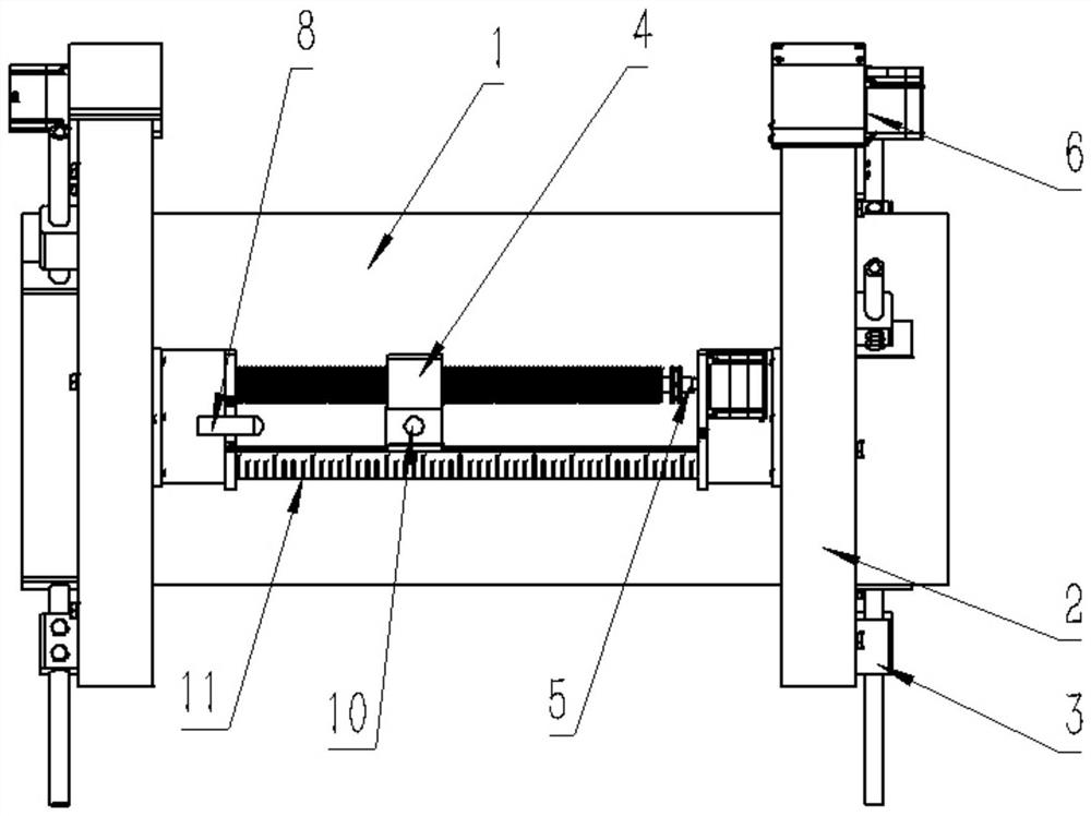
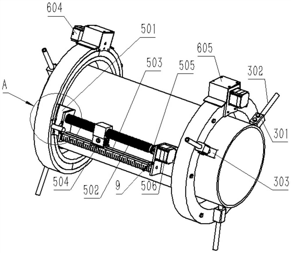
[0042] see Figure 1 to Figure 6 As shown, the present invention is a stud welding tool applied to the pipeline electric field fingerprint method corrosion detection technology, including two correspondingly arranged collars 2 that are sleeved on the outside of the pipeline 1 at the same time, and the outer wall of each collar 2 is fixedly connected with a A plurality of clamping parts 3 matched with the pipeline 1, a sliding block 4 is arranged between the two collars 2, and a stud welding torch station is arranged on the sliding block 4,

[0043] The sliding block 4 is connected with a translation mechanism 5 , and the translation mechanism 5 is connected with a rotation mechanism 6 .

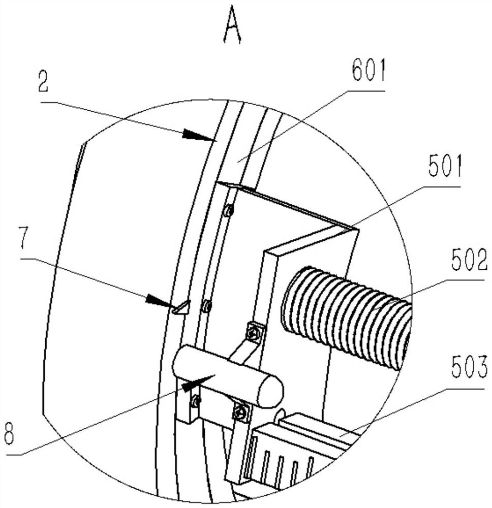
[0044] Each collar 2 is a hollow structure, and the rotating mechanism 6 includes swivels 601 respectively arranged in the two collars 2. The central rotating shaft of the corresponding collar 2 is coaxial, and several rubber wheels 602 are evenly arranged inside each swivel 601, and the rub...

Embodiment 2

[0049] On the basis of embodiment 1, the scale 11 parallel to the track 504 is pasted on the outer surface of the track 504, and a positioning pointer is arranged below the center of the positioning hole 10. The tip of the positioning pointer cooperates with the scale 11 to indicate that the positioning hole 10 is on the axis. direction of movement. The axial moving distance of the positioning hole 10 is no longer judged according to the pitch of the screw rod 502, and the axial positioning is faster and more accurate.

Embodiment 3

[0051] see Figure 7 , on the basis of the above-mentioned embodiment, the other is the same as the above-mentioned embodiment, and the difference from the above-mentioned embodiment is: the outer edge of the bottom of the sliding block 4 is fixedly connected to the support plate 508 through several connecting columns 507, and the bottom of the support plate 508 is fixedly connected and supported Plates 508 are perpendicular to the sliding plate 504, and the bottom surface of the support plate 508 is close to the top surface of the track 503;

[0052] The top surface of the support plate 508 and the bottom surface of the sliding block 4 are symmetrically provided with some pairs of draw-in grooves 509 that are all parallel to the guide rail 503 and mutually parallel to each other from the outside. Positioning holes 10 are provided on the 510, and the diameters of the positioning holes 10 provided on each positioning plate 510 are different.

[0053] When using stud welding to...


PUM


Abstract

The invention provides a stud welding tool applied to a pipeline electric field fingerprint corrosion detection technology, belongs to the technical field of welding, and effectively solves the problems that the monitoring performance is affected due to inaccurate welding positioning of a pipeline monitoring probe and the like. According to the technical scheme, the device comprises two lantern rings which are correspondingly arranged and arranged on the outer side of a pipeline in a sleeving mode at the same time, the outer wall of each lantern ring is fixedly connected with a plurality of clamping pieces matched with the pipeline, a sliding block is arranged between the two lantern rings, a stud welding gun station is arranged on the sliding block, the sliding block is connected with a translation mechanism, and the translation mechanism is connected with a rotating mechanism. The stud welding tool has the beneficial effects that the stud welding tool capable of guaranteeing accurate positioning of pipeline stud welding, consistent welding effect and attractive appearance is provided.

Description

technical field [0001] The invention relates to the field of welding technology, in particular to a stud welding tool applied to the pipeline electric field fingerprint method corrosion detection technology. Background technique [0002] At present, for the installation of pipeline monitoring device probes based on the electric field fingerprint method, the stud welding technology used is mainly to draw the electrode array dot diagram on the pipeline workpiece, and then the technician holds the stud welding torch to weld the stud electrodes on the dots. , there are many shortcomings in this method of welding electrode arrays by hand-held welding torches, such as imprecise welding points, which cannot ensure that the stud electrodes are accurately welded at the drawn dots; the welding torch height and pressure cannot be kept consistent during welding, causing each stud electrode The depth of welding and the burning area of ​​solder joints are different, resulting in inconsist...

Claims


Application Information

Patent Timeline
IPC IPC(8): B23K9/20B23K9/12B23K9/32
CPCB23K9/20B23K9/12B23K9/32B23K9/0026
Inventor 樊户伟陈健飞刘海波李西彦冯启蒙丛雪明彭胜利
Owner CHINA PETROLEUM & CHEM CORP
Learn More