Anti-idling device of handheld electric cutting tool
A cutting tool and anti-idling technology, used in shearing devices, accessories of shearing machines, pipe shearing devices, etc., can solve the problems of affecting service life, waste, equipment damage to power, etc., to eliminate power waste and compact structure. , the effect of strong adaptability
- Summary
- Abstract
- Description
- Claims
- Application Information
AI Technical Summary
Problems solved by technology
Method used
Image

Examples
Deformed example 1
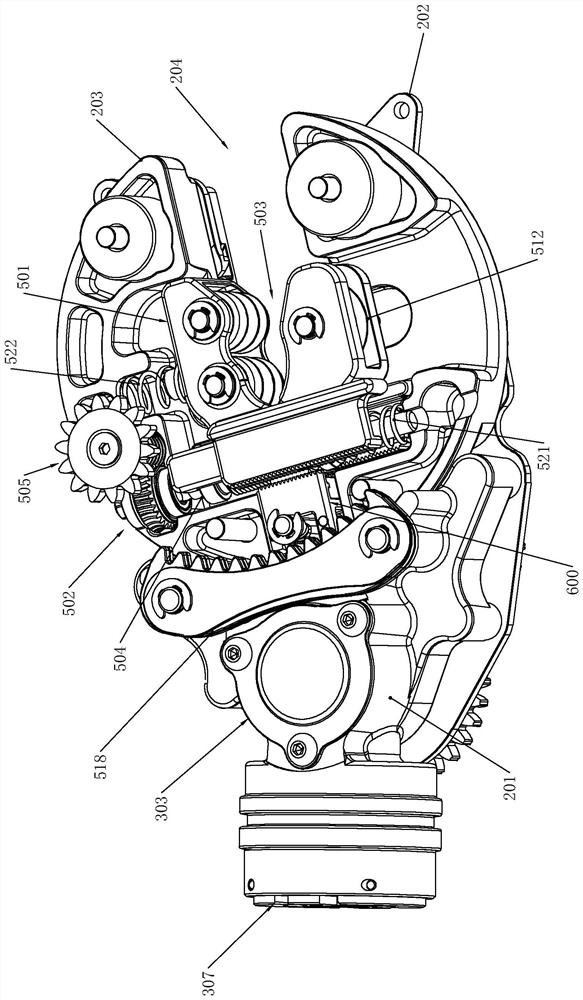
[0097] The threaded part 1 514 can be formed on the sleeve, and then the sleeve is welded to the feed shaft 504 to achieve the purpose of setting the threaded part 1 514 outside the feed shaft 504 .
[0098] Such as Figure 5As shown, in order to cooperate with the reset device 600, a clamping part 1 513 is formed on the end face of the insertion part 1 507;
[0099] The outer wall of the feed shaft 504 forms a threaded part one 514;
[0100] The ends of the reset device 600 are respectively formed with the second clamping part 604 and the second threaded part 606;
[0101] The first clamping part 513 cooperates with the second clamping part 604 , and the first threaded part 514 cooperates with the second threaded part 606 , thereby restricting the free movement of the roller seat 506 and the knife seat 509 .
[0102] The clamping part 1 513 and the clamping part 2 604 can both be tooth-shaped, which can be engaged and clamped; or can be clamped by the cooperation of protrus...
Deformed example 2
[0128] A guide rod can be installed on the roller seat 506 or the knife seat 509, so that the guide bar can move with the roller seat 506 or the knife seat 509.
[0129] In this way, when the pipe is not clamped, the end of the guide rod is close to the sensor 701; when the pipe is clamped, the clamping position is stretched, and at this time, the roller seat 506 or the knife seat 509 is displaced, so that the guide rod Retract in the cutting seat, that is, the end of the guide rod is away from the sensor 701 .
[0130] Such as Figure 7-Figure 10 As shown, the structure of the reset device 600 is as follows.
[0131] The reset device 600 includes a knife limiting mechanism 601 and an adjusting mechanism 602;
[0132] The knife limiting mechanism 601 is installed on the side of the knife feeding device 500, and the adjusting mechanism 602 is installed on the rear end of the knife limiting mechanism 601. The front end of the knife limiting mechanism 601 is used to clip and cl...
Deformed example 3
[0143] The above-mentioned limiting block 603 can also be integrally formed with the cutting seat 203, and it can also be reset by continuing to reverse it when resetting.
[0144] The adjustment mechanism 602 includes a push piece 607, a reset piece 608 and an elastic piece 2 609;
[0145] The pusher 607 is passed through the cutting seat 203, and the part inside the cutting seat 203 is an eccentric shaft. The side wall of the eccentric shaft is against the rear end of the limit block 603. A swing rod 616 is formed along the side wall of the cutting seat 203, and the end of the swing rod 616 protrudes to form a rotating protrusion 615;
[0146] The quantity of the second elastic member 609 is two, all of which are arranged in the cutting seat 203, and the end of the second elastic member 609 is fixed on the pin shaft, and the other end is respectively connected to the side of the rear end of the limit block 603, and the eccentric shaft is located at the two sides. Between tw...
PUM
 Abstract
Description
Claims
Application Information
 - R&D
- Intellectual Property
- Life Sciences
- Materials
- Tech Scout
- Unparalleled Data Quality
- Higher Quality Content
- 60% Fewer Hallucinations
Browse by: Latest US Patents, China's latest patents, Technical Efficacy Thesaurus, Application Domain, Technology Topic, Popular Technical Reports.
© 2025 PatSnap. All rights reserved.Legal|Privacy policy|Modern Slavery Act Transparency Statement|Sitemap|About US| Contact US: help@patsnap.com