
Pressing hemostasis device used after angiocardiography

A cardiovascular and control device technology, applied in the field of medical equipment, can solve problems such as high labor intensity, arm collision, and inability to press patients' wounds

Inactive Publication Date: 2022-05-06
王莉
View PDF0 Cites 0 Cited by
  • Summary
  • Abstract
  • Description
  • Claims
  • Application Information

AI Technical Summary

Problems solved by technology

[0002] Cardiovascular angiography is a very valuable method for diagnosing cardiovascular diseases; after the percutaneous puncture of cardiovascular angiography, manual pressure is generally used for hemostasis at the puncture site when the radial artery is extubated and after extubation, although It can achieve the purpose of hemostasis, but it needs to be pressed continuously for a long time, and usually the patient needs to press with the hand without the needle, but when the patient is unconscious or asleep, the medical staff needs to press, which is very labor-intensive. The personnel increase the difficulty of the work, so a pressing hemostatic device is needed for pressing hemostasis
[0003] The existing pressing hemostasis device has a simple structure, and cannot quickly press the patient's wound during use, and when hemostasis, the patient's arm is vulnerable to external collisions, which affects the hemostasis effect, so the above problems need to be solved

Method used


Image

  • Pressing hemostasis device used after angiocardiography
  • Pressing hemostasis device used after angiocardiography
  • Pressing hemostasis device used after angiocardiography

Examples


Embodiment 1

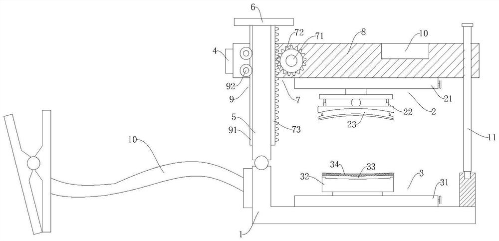
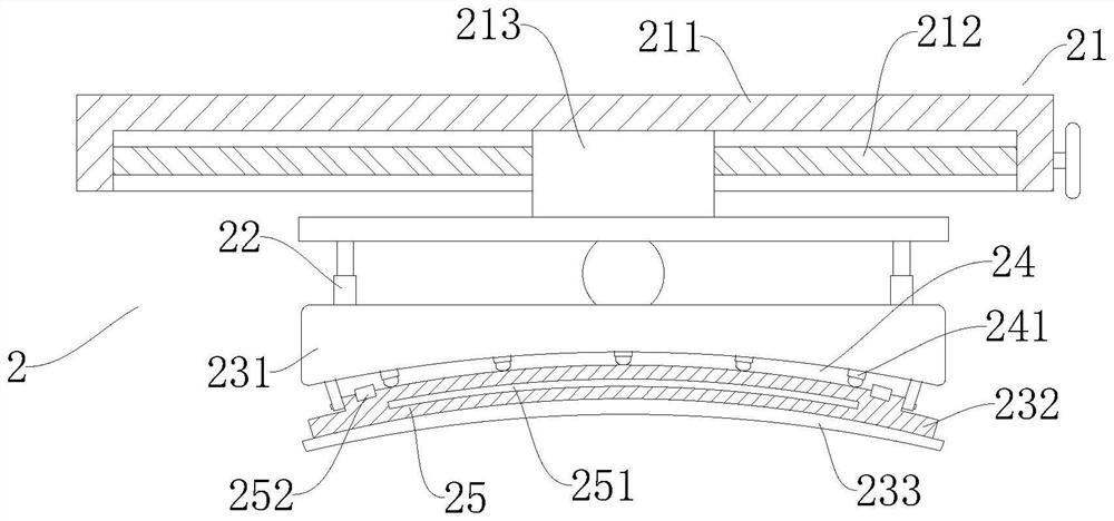
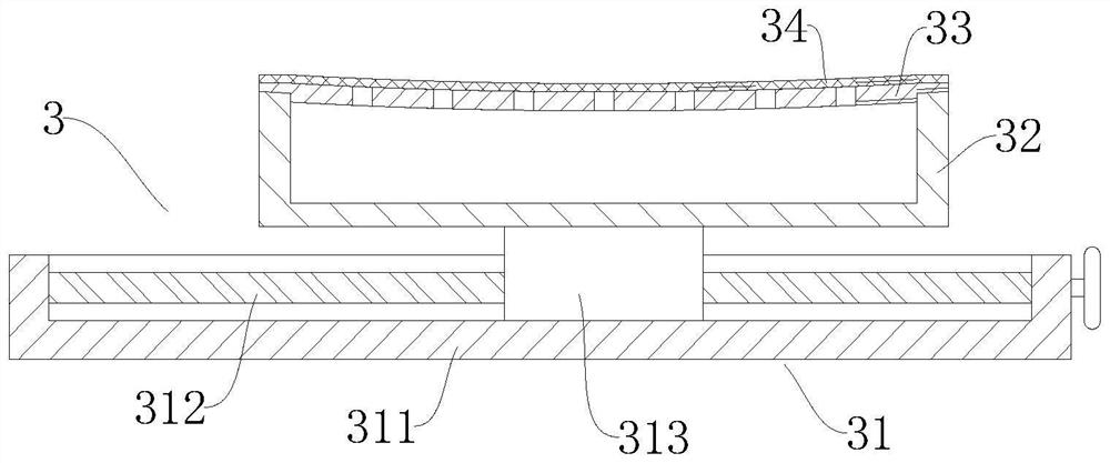
[0034] Please refer to Figure 1-Figure 3 , the present embodiment provides a compression hemostasis device after cardiovascular angiography, which includes a support base 1, a lifting mechanism and a hemostasis mechanism. "type structure, a movable bracket 10 is provided on one side of the above-mentioned support seat 1; the above-mentioned hemostatic mechanism includes an upper hemostatic device 2 and a lower hemostatic device 3, the above-mentioned upper hemostatic device 2 is arranged on the above-mentioned lifting mechanism, and the above-mentioned lower hemostatic device 3 is arranged on the above-mentioned support Seat 1; also includes a temperature control device and a control device 4, the temperature control device is set on the upper hemostasis device 2, and the temperature control device, the lifting mechanism and the hemostasis mechanism are all electrically connected to the control device 4.

[0035] In this embodiment, the support base 1 can provide stable suppo...

Embodiment 2

[0040] Please refer to Figure 1-Figure 3 In this embodiment, on the basis of some of the above-mentioned embodiments, the above-mentioned lifting mechanism includes a first column 5, a limit plate 6, a drive assembly 7, a horizontal plate 8 and a second column 11, and the above-mentioned first column 5 and the above-mentioned second column 11 is arranged on both sides of the above-mentioned horizontal plate 8, the bottom end of the above-mentioned first column 5 is hinged with the above-mentioned support seat 1, the bottom end of the above-mentioned second column 11 is detachably connected with the above-mentioned support seat 1, and the above-mentioned limiting plate 6 is arranged on the above-mentioned On the top of the first column 5, the above-mentioned horizontal plate 8 is slidably arranged on the above-mentioned first column 5, the above-mentioned upper hemostasis device 2 is arranged on the above-mentioned horizontal plate 8, and the above-mentioned driving assembly 7 ...

Embodiment 3

[0045] Please refer to Figure 1-Figure 3 In this embodiment, on the basis of some of the above-mentioned embodiments, the above-mentioned driving assembly 7 includes a driving motor 71, a power gear 72 and a gear bar 73, and the above-mentioned horizontal plate 8 is provided with a slide groove, and the inside of the above-mentioned horizontal plate 8 is close to the above-mentioned slide groove. The side is provided with installation groove, and above-mentioned installation groove communicates with above-mentioned slide groove, and above-mentioned drive motor 71 and above-mentioned power gear 72 are all arranged in above-mentioned installation groove, and above-mentioned power gear 72 is arranged at the transmission output end of above-mentioned drive motor 71, and above-mentioned gear bar 73 is disposed on one side of the first column 5 , the power gear 72 is meshed with the gear rack 73 , and the drive motor 71 is electrically connected with the control device 4 .

[0046]...


PUM


Abstract

The invention discloses a pressing hemostasis device used after angiocardiography, and relates to the technical field of medical instruments. A pressing hemostasis device used after angiocardiography comprises a supporting seat, a lifting mechanism and a hemostasis mechanism, the lifting mechanism is hinged to the supporting seat, the lifting mechanism and the supporting seat form a square structure in a surrounding mode, and a movable support is arranged on one side of the supporting seat; the hemostasis mechanism comprises an upper hemostasis device and a lower hemostasis device, the upper hemostasis device is arranged on the lifting mechanism, and the lower hemostasis device is arranged on the supporting seat; the device further comprises a temperature control device and a control device, the temperature control device is arranged on the hemostasis device, the temperature control device, the lifting mechanism and the hemostasis mechanism are all electrically connected with the control device, when the device is used, compression hemostasis can be rapidly conducted on a postoperative wound of a patient, the lifting mechanism and the supporting base form a square-shaped structure in a surrounding mode, the arm of the patient can be protected inside, and the device is convenient to use. The collision of the outside to the arms of the patient is prevented.

Description

technical field [0001] The invention relates to the technical field of medical devices, in particular to a compression hemostasis device after angiography. Background technique [0002] Cardiovascular angiography is a very valuable method for diagnosing cardiovascular diseases; after the percutaneous puncture of cardiovascular angiography, manual pressing is generally used to stop bleeding at the puncture site when the radial artery is extubated and after extubation, although It can achieve the purpose of hemostasis, but it needs to be pressed continuously for a long time, and usually the patient needs to press with the hand without the needle, but when the patient is unconscious or asleep, the medical staff needs to press, and the labor intensity is very high. The personnel have increased work difficulty, therefore need a kind of pressing hemostasis device to carry out pressing hemostasis. [0003] The existing pressing hemostasis device has a simple structure and cannot q...

Claims


Application Information

Patent Timeline
IPC IPC(8): A61B17/12A61B90/14
CPCA61B17/12A61B90/14A61B2017/12004
Inventor 王莉
Owner 王莉
Learn More