
Machining method of taper pin hole

A processing method, the technology of taper pin hole, which is applied in the processing field of taper pin hole, can solve the problems of reducing processing efficiency, increasing the difficulty of reaming, uneven force, etc., and achieve the effect of reducing processing difficulty, improving processing efficiency and processing quality

Pending Publication Date: 2022-05-03
NANJING HIGH ACCURATE MARINE EQUIP CO LTD +1
View PDF12 Cites 0 Cited by
  • Summary
  • Abstract
  • Description
  • Claims
  • Application Information

AI Technical Summary

Problems solved by technology

Due to the large size of the cone reamer, the cutting diameter of the reamer is above 80mm, the reaming resistance on each cutting section of the cone reamer is relatively large, which increases the difficulty of reaming and greatly reduces the processing efficiency
At the same time, this kind of cone reamer has a large size and cannot be made into a floating reamer. The cone reamer rigidly connected with the machine tool is subjected to uneven force during reaming, which seriously affects the roughness of the cone pin hole and the coloring contact accuracy.

Method used


Image

  • Machining method of taper pin hole
  • Machining method of taper pin hole

Examples


Embodiment Construction

[0030] In order to make the technical problems solved by the present invention, the technical solutions adopted and the technical effects achieved clearer, the technical solutions of the present invention will be further described below in conjunction with the accompanying drawings and through specific implementation methods. It should be understood that the specific embodiments described here are only used to explain the present invention, rather than to limit the present invention. In addition, it should be noted that, for the convenience of description, only the parts related to the present invention are shown in the drawings but not all of them.

[0031] In the description of the present invention, unless otherwise clearly specified and limited, the terms "connected", "connected" and "fixed" should be understood in a broad sense, for example, it can be a fixed connection, a detachable connection, or an integrated ; It can be a mechanical connection or an electrical connect...


PUM


Abstract

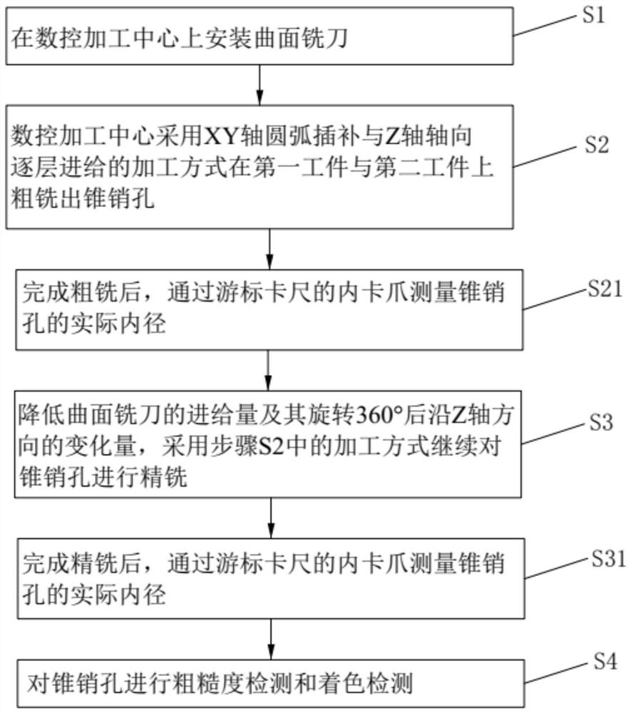
The invention relates to the technical field of workpiece machining, and particularly discloses a taper pin hole machining method which is used for machining taper pin holes in a first workpiece and a second workpiece which are connected with each other and specifically comprises the steps that S1, a curved surface milling cutter is installed on a numerical control machining center; and S2, the numerical control machining center roughly mills taper pin holes in the first workpiece and the second workpiece in the machining mode of XY-axis arc interpolation and Z-axis axial layer-by-layer feeding. And S3, the feeding amount of the curved-surface milling cutter and the variable quantity of the curved-surface milling cutter in the Z-axis direction after the curved-surface milling cutter rotates by 360 degrees are reduced, and finish milling continues to be conducted on the taper pin hole in the machining mode in the step S2. A curved surface milling cutter is installed in the numerical control machining center, the taper pin holes are roughly milled in the first workpiece and the second workpiece in the machining mode of XY-axis arc interpolation and Z-axis axial layer-by-layer feeding, then finish milling is continuously conducted on the taper pin holes, and therefore the taper pin holes are rapidly machined, the machining difficulty of the taper pin holes is lowered, and the machining efficiency of the taper pin holes is improved. And the machining efficiency and the machining quality of the taper pin hole are improved.

Description

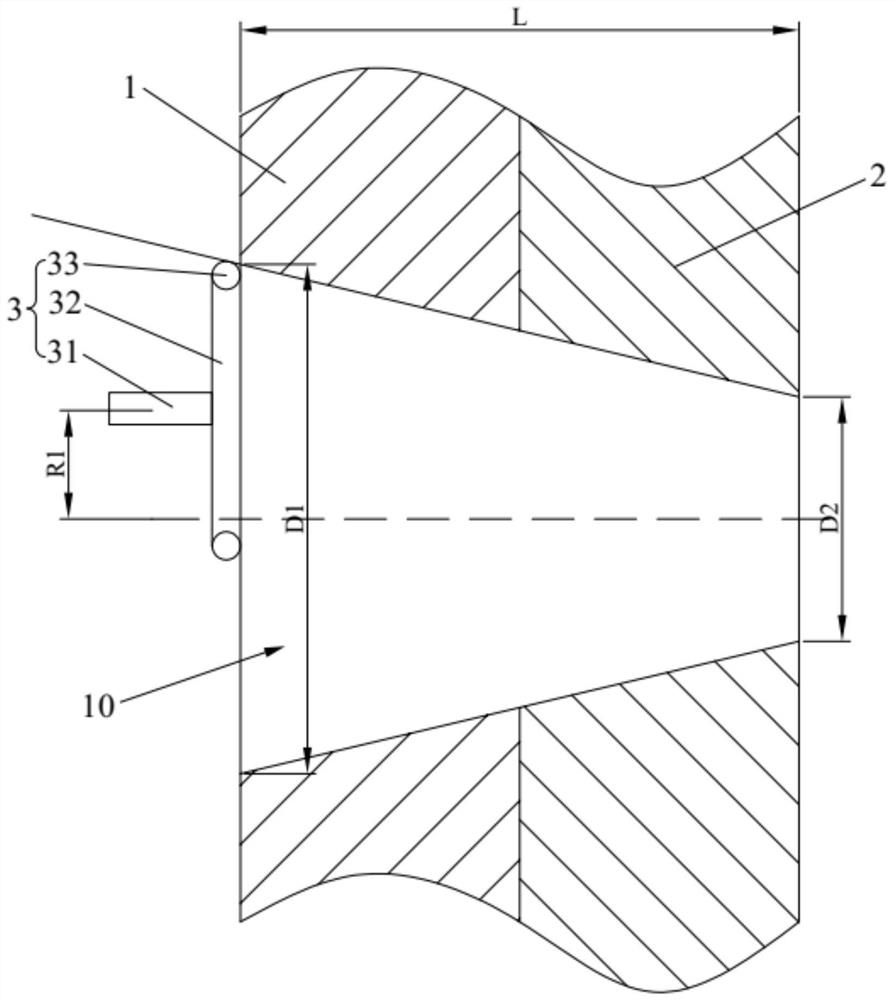
technical field [0001] The invention belongs to the technical field of workpiece processing, and in particular relates to a processing method for taper pin holes. Background technique [0002] The taper pin hole is a light hole that is precisely matched with the taper pin. The function of the taper pin hole and the taper pin is to connect the two workpieces together, and prevent the gap between the two workpieces through the shear resistance of the taper pin itself. Relative rotation occurs. [0003] When machining extra-large taper pin holes, the first workpiece and the second workpiece are connected by taper pins. The diameter D1 of the large end of the taper pin hole of the first workpiece and the second workpiece is greater than or equal to 80mm, the diameter of the small end is D2, the width of the first workpiece and the second workpiece (the length of the taper pin hole) is L, and the taper of the taper pin hole It is (D1-D2) / L. It is generally required that the ro...

Claims


Application Information

Patent Timeline
Patent Type & Authority Applications(China)
IPC IPC(8): B23P15/00
CPCB23P15/00
Inventor 杨欣荣王炯徐阳舒永东谢贵王力余智洪刘智佩李泽军
Owner NANJING HIGH ACCURATE MARINE EQUIP CO LTD
Learn More