
Real-time monitoring system for industrial production equipment

An industrial production equipment and real-time monitoring technology, applied in the field of industrial production, can solve problems such as difficult to check out products, achieve the effect of improving the pass rate, improving the monitoring effect and accuracy rate, and ensuring the monitoring effect

Inactive Publication Date: 2022-04-29
研行(苏州)工业科技有限公司
View PDF0 Cites 0 Cited by
  • Summary
  • Abstract
  • Description
  • Claims
  • Application Information

AI Technical Summary

Problems solved by technology

With the continuous advancement of science and technology, industrial production has gradually begun to be automated, and production efficiency has been further improved. At present, in the production process of industrial automation, staff are still required to manually monitor the products on the production equipment assembly line. Press the stop button in time for qualified products, and then remove the unqualified products through the reject system on the production equipment, so as to ensure the quality and effect of industrial production products. However, this method of manual monitoring can only check the appearance of the products However, it is difficult to check whether there are any defects inside the product, such as cracks, blisters, pores, white spots, inclusions, etc., whether the weld is qualified, find out whether there are hidden defects, and then determine whether the product is qualified or not. For this reason, we have proposed A real-time monitoring system for industrial production equipment to overcome the problems raised above

Method used


Image

  • Real-time monitoring system for industrial production equipment
  • Real-time monitoring system for industrial production equipment
  • Real-time monitoring system for industrial production equipment

Examples


Embodiment Construction

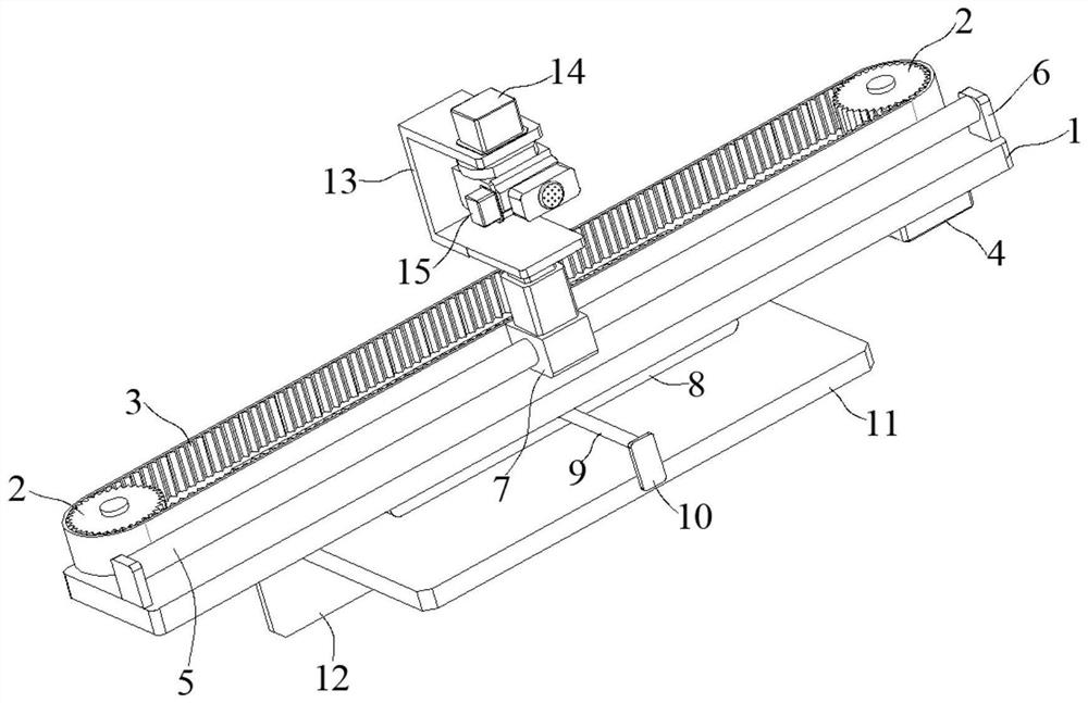
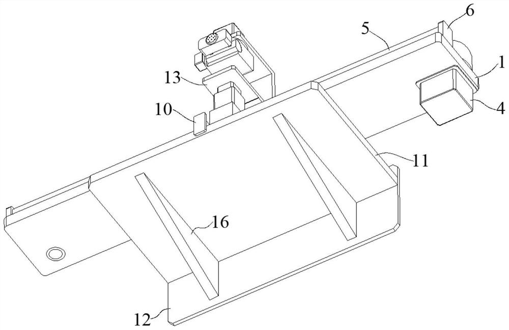
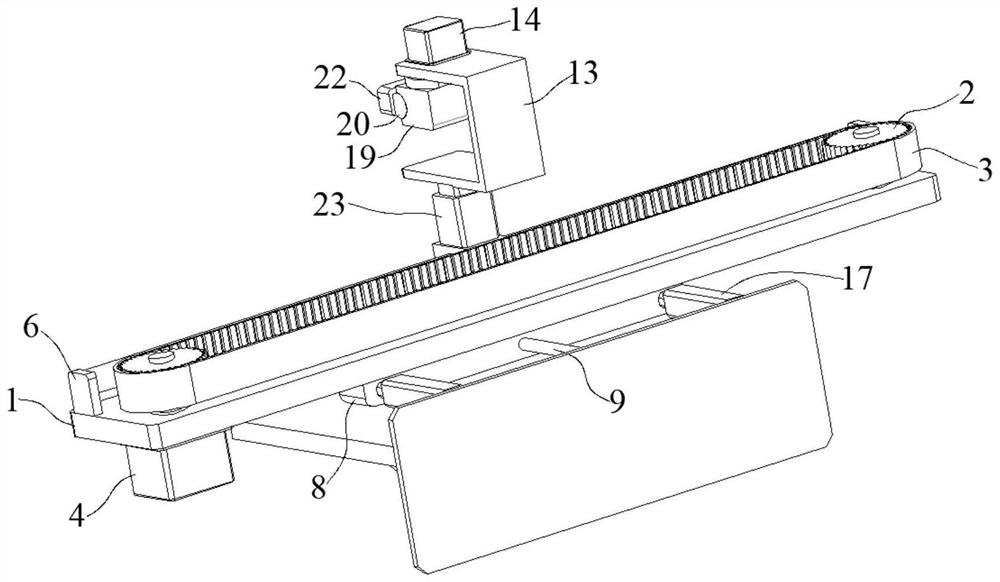
[0026] The following is attached Figure 1-4 The principles and features of the present invention are described, and the examples given are only used to explain the present invention, and are not used to limit the scope of the present invention. In the following paragraphs the invention is described more specifically by way of example with reference to the accompanying drawings. Advantages and features of the present invention will be apparent from the following description and claims. It should be noted that all the drawings are in a very simplified form and use imprecise scales, and are only used to facilitate and clearly assist the purpose of illustrating the embodiments of the present invention.

[0027] It should be noted that when a component is said to be "fixed" to another component, it can be directly on the other component or there can also be an intervening component. When a component is said to be "connected" to another component, it may be directly connected to ...


PUM


Abstract

The invention relates to a real-time monitoring system for industrial production equipment, which comprises a supporting platform, synchronous belt wheels are arranged on the left side and the right side above the supporting platform, a rotating rod is fixedly inserted into an inner cavity of each synchronous belt wheel, and the bottom ends of the two rotating rods are rotationally connected with the supporting platform. A first servo motor is fixedly connected to the position, corresponding to one synchronous belt wheel, of the bottom of the supporting platform, an output shaft of the first servo motor penetrates through the supporting platform and is connected with the bottom end of the corresponding rotating rod, and the peripheries of the two synchronous belt wheels are jointly sleeved with a synchronous belt working in cooperation with the two synchronous belt wheels. A monitoring module is arranged on the outer wall of the synchronous belt, and an adjustable base is arranged at the bottom of the supporting platform. According to the system, quality monitoring can be conveniently carried out on the interiors of the products on a production equipment assembly line, so that whether the interiors of the products have dark injuries or not can be effectively detected, the monitoring effect of the products is guaranteed, workers can timely remove unqualified products, and the percent of pass of the products is improved.

Description

technical field [0001] The invention relates to the technical field of industrial production, in particular to a real-time monitoring system for industrial production equipment. Background technique [0002] Industrial production is mainly carried out in factories. In a factory, labor (workers, technicians, etc.) uses power (fuel, electricity) and machinery to turn raw materials into products. A raw material can produce different products, and a product may be processed, assembled or compounded from a variety of raw materials. The normal production of a factory requires not only basic conditions such as labor force, power, and plant equipment, but also is restricted by factors such as science and technology, government policies, funds, and management. Industrial products must be sold in the market in order to realize their value. As a result, numerous large and small factories are constantly looking for their own positions in the market and gain profits from selling produ...

Claims


Application Information

Patent Timeline
Patent Type & Authority Applications(China)
IPC IPC(8): G06Q10/06G06Q50/04
CPCG06Q10/063114G06Q10/06395G06Q50/04Y02P90/30
Inventor 张晋维张铮
Owner 研行(苏州)工业科技有限公司
Learn More