Logging-while-drilling instrument with high-strength anti-seismic function for petroleum drilling
A logging-while-drilling tool and oil drilling technology, which is applied in wellbore/well components, measurement, earthwork drilling and production, etc., which can solve the problem of damage to logging instruments, the reduction of shock absorption effect of rubber shock absorbing rings, and reduce the use of logging instruments Life and other issues, to avoid collision damage and avoid excessive reset speed
- Summary
- Abstract
- Description
- Claims
- Application Information
AI Technical Summary
Problems solved by technology
Method used
Image
Examples
Embodiment 1
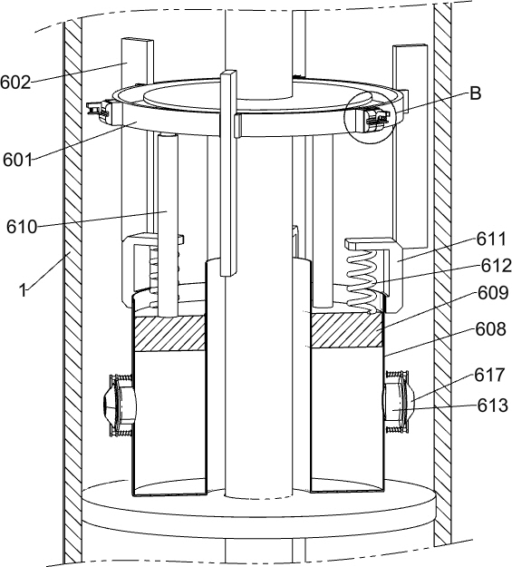
[0032] A logging-while-drilling tool for oil drilling with high-strength anti-seismic function, such as Figure 1-Figure 12 As shown, it includes an outer drill collar 1, an inner drill collar 2, a logging instrument 3, a circumferential shock absorbing mechanism, a hydraulic shock absorbing mechanism, and an anti-shock mechanism. The middle part of the outer drill collar 1 is provided with an inner drill collar 2. The instrument 3 is installed in the cavity formed by the outer drill collar 1 and the inner drill collar 2, and the circumferential damping mechanism is arranged between the logging instrument 3 and the outer surface of the inner drill collar 2, which is used for hydraulic shock absorption to absorb torsional impact The mechanism is arranged on the lower side of the logging instrument 3, and the anti-shock mechanism is arranged on the lower side of the hydraulic damping mechanism, and the anti-shock mechanism cooperates mechanically with the hydraulic damping mechan...
Embodiment 2
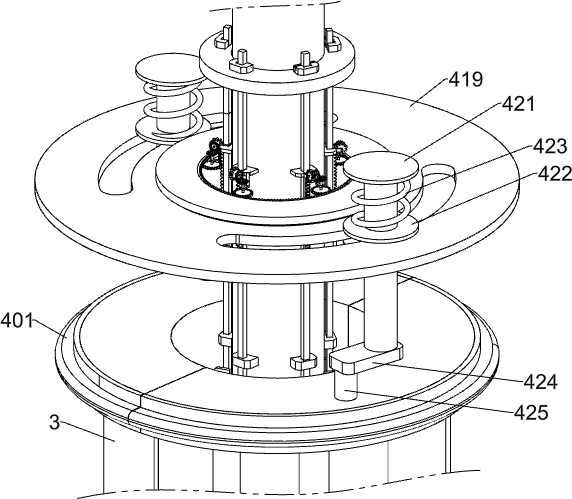
[0035] On the basis of Example 1, such as Figure 2-Figure 6 As shown, the circumferential damping mechanism includes a damping rubber ring 401, an annular plate 402, a first fixed shell 403, a sliding block 404, a first spring 405, a spring leaf 406, a first guide plate 407, a connecting rod 408, a first A fixed seat 409, the first fixed ring 410, the first stopper 411, the second fixed seat 412, the rotating shaft 413, the one-way gear 414, the first bevel gear 415, the connecting seat 416, the second bevel gear 417, the straight The gear 418, the second fixed ring 419, the rotating ring 420, the first sliding rod 421, the first sliding plate 422, the second spring 423, the rotating block 424 and the connecting shaft 425, the upper and lower outer surfaces of the logging instrument 3 are fixed respectively. A shock-absorbing rubber ring 401 is connected to absorb the impact force. The outer ring surface of the shock-absorbing rubber ring 401 is convex, and the inner ring sur...
Embodiment 3
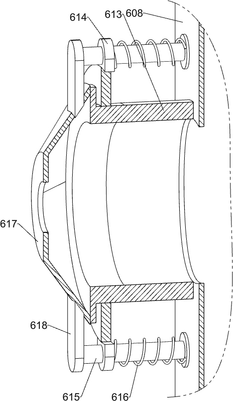
[0044] On the basis of Example 2, such as Figure 13 As shown, it also includes a circular tube 613, an annular frame 614, a third sliding rod 615, a seventh spring 616, a sealing shell 617 and a connecting plate 618, and the left and right parts of the annular shell 608 are respectively communicated with a circular tube 613. The outer surface of the shaped tube 613 is fixedly connected with a ring frame 614, and the upper and lower parts of the ring frame 614 are respectively slidably connected with a third sliding rod 615, and the outer surface of the third sliding rod 615 is slidably connected with a seventh spring 616, and the seventh spring 616 The two ends of the two circular tubes 613 are fixedly connected to the ring frame 614 and the third sliding rod 615 respectively. The outer ends of the two circular tubes 613 are provided with a sealing shell 617. The circular hole for circulation, the sealing shell 617 is in sealing fit with the circular tube 613 , the upper and ...
PUM
 Abstract
Description
Claims
Application Information
 - R&D Engineer
- R&D Manager
- IP Professional
- Industry Leading Data Capabilities
- Powerful AI technology
- Patent DNA Extraction
Browse by: Latest US Patents, China's latest patents, Technical Efficacy Thesaurus, Application Domain, Technology Topic, Popular Technical Reports.
© 2024 PatSnap. All rights reserved.Legal|Privacy policy|Modern Slavery Act Transparency Statement|Sitemap|About US| Contact US: help@patsnap.com


