Auxiliary threshing and cleaning device of rice harvester
A cleaning device and harvester technology, applied in threshing equipment, agricultural machinery and tools, agriculture, etc., can solve the problems that cannot be screened separately, dusty sand and gravel, general threshing effect, etc., and achieve high-quality screening and discharging Good effect, good threshing effect
- Summary
- Abstract
- Description
- Claims
- Application Information
AI Technical Summary
Problems solved by technology
Method used
Image
Examples
Embodiment 1
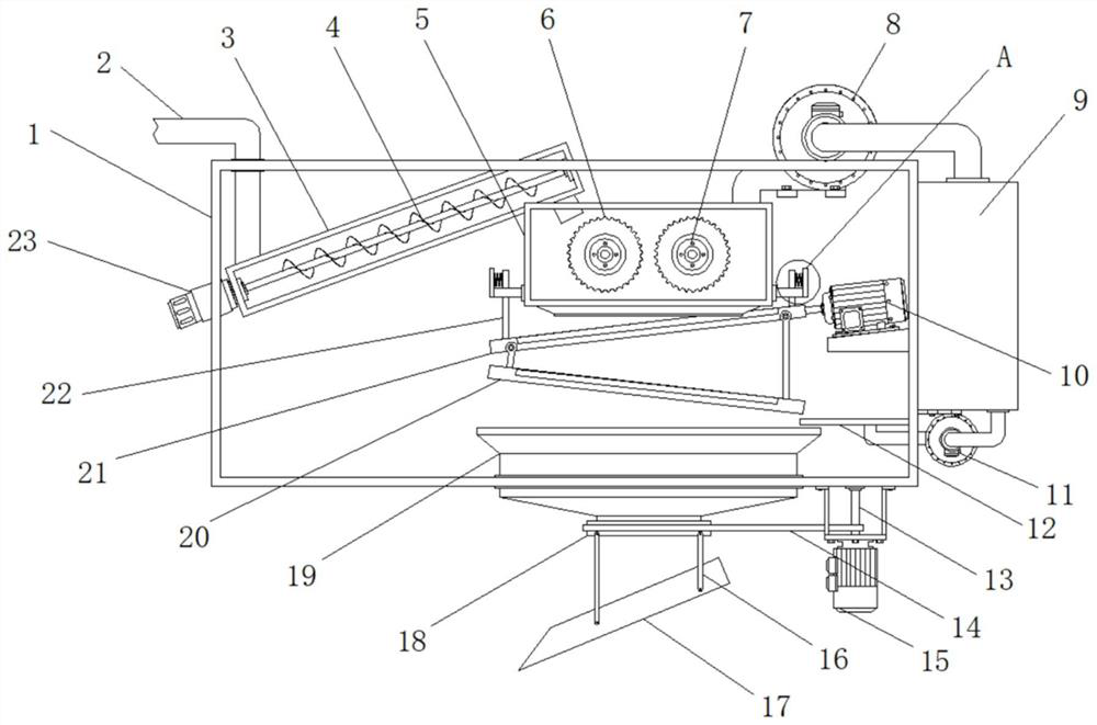
[0020] Example 1: See Figure 1-4 , a rice harvester auxiliary threshing and cleaning device, comprising a device body 1 and a feed pipe 2, a side of the top of the device body 1 is provided with a feed pipe 2, the bottom of the feed pipe 2 is provided with a conveying chamber 3, the conveying chamber 3 is connected with lifting auger 4, and one side of delivery chamber 3 is fixedly connected with first driving motor 23, and the output end of first driving motor 23 is fixedly connected with lifting auger 4 through a shaft coupling. The other side is provided with a threshing chamber 5, and two sets of threshing rollers 6 are installed inside the threshing chamber 5, and two sets of second driving motors 7 are installed at one end of the threshing chamber 5, and the output ends of the second driving motors 7 are respectively connected through couplings. Fixedly connected with the threshing roller 6;
[0021] Specifically, such as figure 1 with Figure 4 As shown, the paddy r...
Embodiment 2
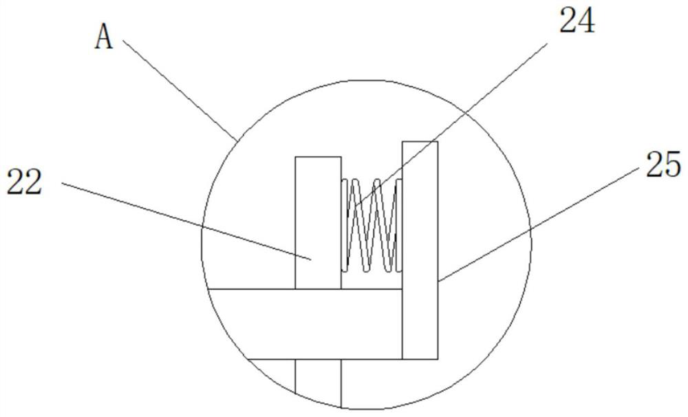
[0022] Embodiment 2: a first fan 8 is installed above the threshing chamber 5, and the output end of the first fan 8 is provided with a surplus material box 9, and the surplus material box 9 is installed on the other side of the device body 1, on both sides of the bottom of the threshing chamber 5 The bottom end of the bottom end is fixedly connected with fixed frame 25 respectively, and the inside of fixed frame 25 is movably connected with movable frame 22 respectively, is fixedly connected with spring 24 between the top of movable frame 22 and the sidewall of fixed frame 25, and the bottom of movable frame 22 The first sieve plate 21 is fixedly connected, and the bottom end of the first sieve plate 21 is fixedly connected with the second sieve plate 20. The inclination directions of the first sieve plate 21 and the second sieve plate 20 are opposite, and the other side inside the device body 1 The vibration motor 10 is fixedly connected, the eccentric shaft of the vibration ...
Embodiment 3
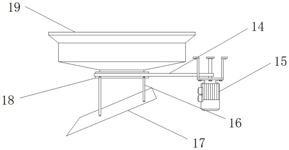
[0024] Embodiment 3: The bottom end of the device body 1 is equipped with a discharge cylinder 19, the bottom end of the discharge cylinder 19 is movably socketed with a turntable 18, and the other side of the turntable 18 is equipped with a third drive motor 15, the third drive motor 15 The output end of the motor is fixedly connected with a rotating rod 13 through a coupling, and a transmission belt 14 is arranged between the rotating rod 13 and the turntable 18. The bottom end of the turntable 18 is fixedly connected with a hanger 16, and the bottom end of the hanger 16 is hinged with a discharge Plate 17, the discharge plate 17 is semi-arc;
[0025] Specifically, such as figure 1 with image 3 As shown, the grains drop from the discharge cylinder 19 onto the discharge plate 17, and the bagging can be completed by placing the collecting container on the bottom of the discharge plate 17, and the output end of the third driving motor 15 is driven by the rotation of the rotat...
PUM
 Abstract
Description
Claims
Application Information
 - Generate Ideas
- Intellectual Property
- Life Sciences
- Materials
- Tech Scout
- Unparalleled Data Quality
- Higher Quality Content
- 60% Fewer Hallucinations
Browse by: Latest US Patents, China's latest patents, Technical Efficacy Thesaurus, Application Domain, Technology Topic, Popular Technical Reports.
© 2025 PatSnap. All rights reserved.Legal|Privacy policy|Modern Slavery Act Transparency Statement|Sitemap|About US| Contact US: help@patsnap.com


