
Portable injection mold for manufacturing intravascular stent

An injection mold and vascular stent technology, applied in the field of portable injection molds, can solve problems such as affecting the normal use of the stent, burrs on the sides of the stent, and small size of the vascular stent, and achieves simple molding method, safe and convenient use, and reduction of injection molding completion. effect of time

Pending Publication Date: 2022-04-26
LIAONING UNIVERSITY OF TECHNOLOGY
View PDF0 Cites 0 Cited by
  • Summary
  • Abstract
  • Description
  • Claims
  • Application Information

AI Technical Summary

Problems solved by technology

[0004] The present invention provides a convenient injection mold for making vascular stents, which can effectively solve the problem of complex production steps in the injection molding process of vascular stents proposed in the above-mentioned background technology. The normal use of the bracket, and the edge of the injection molded bracket will have burrs, which need to be processed again later

Method used


Image

  • Portable injection mold for manufacturing intravascular stent
  • Portable injection mold for manufacturing intravascular stent
  • Portable injection mold for manufacturing intravascular stent

Examples


Embodiment

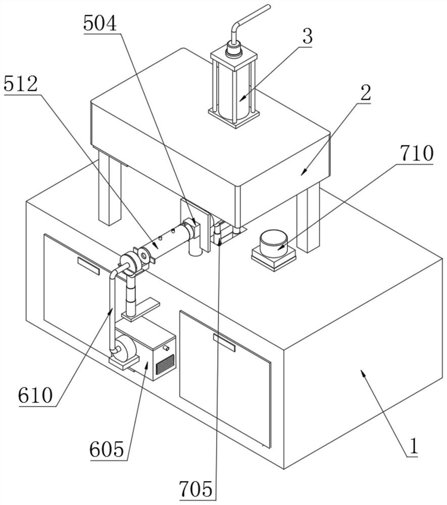
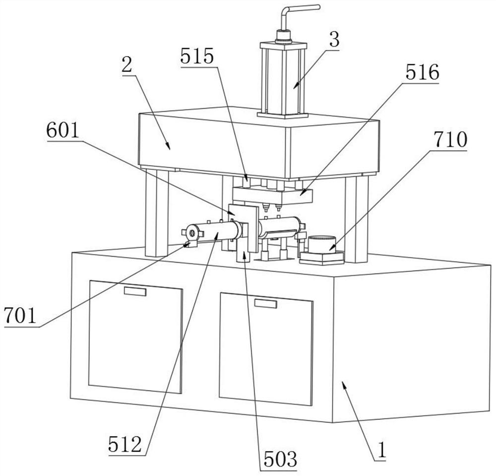
[0044] Example: such as Figure 1-7 As shown, the present invention provides a technical solution, a portable injection mold for making vascular stents, including a workbench 1, a mold base 2 is fixedly installed on the top of the workbench 1, and a liquid injection mold is fixedly installed in the middle of the top of the mold base 2 The pipe 3 and the top of the liquid injection pipe 3 are fixedly connected with a connecting pipe 4, and one end of the connecting pipe 4 is connected with an external raw material melting furnace;

[0045] The middle part of the top of the workbench 1 is fixed with a convenient injection molding mechanism 5, which is equipped with double stations, and the injection molded workpieces are removed at the same time as the injection molding, and the injection molding is carried out alternately, which improves the work efficiency;

[0046] The convenient injection molding mechanism 5 includes a card slot 501, a rotating block 502, a rotating rod 503,...


PUM


Abstract

A mold base is fixedly installed at the top end of a workbench, a liquid injection pipe is fixedly installed in the middle of the top end of the mold base, a connecting pipeline is fixedly connected to the top end of the liquid injection pipe, and a convenient injection molding mechanism is fixedly installed in the middle of the top end of the workbench. The hydraulic telescopic rod can drive the lifting mold plate and the injection molding head to move up and down, the injection molding head is directly inserted into an injection molding pipe, injection molding raw materials are downwards injected into the attaching position of the outer sealing sleeve and the injection molding sleeve, and the outer sealing sleeve is tightly attached to the outer surface of the injection molding sleeve, so that the injection molding raw materials only flow along an injection molding rail groove; the intravascular stent is subjected to injection molding in the injection molding track groove, the molding mode is simple and convenient, injection molding raw materials cannot permeate, it is guaranteed that burrs cannot occur, the two injection molding heads and the injection molding pipe are subjected to injection molding at the same time, the raw materials can uniformly flow downwards, it is guaranteed that the intravascular stent subjected to injection molding is more uniform in structure, and the situation that due to insufficient raw materials, a part of the intravascular stent is sunken is avoided.

Description

technical field [0001] The invention relates to the technical field of injection molds, in particular to a convenient injection mold for making vascular stents. Background technique [0002] Vascular stent refers to the placement of internal stents in the diseased segment on the basis of lumen balloon expansion to achieve the purpose of supporting the stenotic and occluded segment of the vessel, reducing the elastic retraction and reshaping of the vessel, and maintaining the smooth blood flow in the lumen. Internal stents also have the function of preventing restenosis. They are mainly divided into coronary stents, cerebrovascular stents, renal artery stents, aortic stents, etc. Vascular stents can be divided into self-expandable and balloon-expandable according to the way they are deployed in the blood vessel. Two types, the former, such as Z-shaped stents and mesh-shaped stents, which can expand themselves in blood vessels, while the latter are inelastic and attached to bl...

Claims


Application Information

Patent Timeline
Patent Type & Authority Applications(China)
IPC IPC(8): B29C45/06B29C45/13B29C45/18B29C45/22B29C45/27B29C45/26B29C45/73B29C45/17
CPCB29C45/06B29C45/13B29C45/18B29C45/22B29C45/27B29C45/26B29C45/73B29C45/17Y02P70/10
Inventor 魏云波白建更赵海涛王瑞
Owner LIAONING UNIVERSITY OF TECHNOLOGY
Learn More