
An optical time domain reflectometer and its positioning method for communication optical fibers between 5G base stations

A technology between optical time domain reflectometers and base stations, applied in optical fiber transmission, optical fiber radio, electrical components, etc., can solve problems such as cable detection interference, dust accumulation, etc., and achieve the effect of reducing excessive bending

Active Publication Date: 2022-06-07
中国人民解放军军事科学院战争研究院
View PDF11 Cites 0 Cited by
  • Summary
  • Abstract
  • Description
  • Claims
  • Application Information

AI Technical Summary

Problems solved by technology

[0003] In the prior art, the patent with the publication number CN213779452U discloses a device for optical time domain reflectometer optical fiber testing, including a storage box, the inner walls of both sides of the storage box are provided with pulley grooves, and the two pulleys The inner walls on both sides of the groove are rollingly connected with pulleys, and the sides of the two pulleys close to each other are fixedly connected with the same optical time domain reflectometer. The optical time domain reflectometer forms the brake component of the brake. One side of the storage box is provided with a groove, and the inner walls of both sides of the groove are provided with chutes, and the two chutes are slidably connected. There is a slider, and the structure of the above-mentioned patent is simple. The optical time domain reflectometer can be stored in the storage box through the pulley groove and the pulley, and the top of the locking block is staggered from the card slot by rotating the block, so that the optical time domain reflectometer can be formed. Move the OTDR to prevent the OTDR from the storage box, and flip the OTDR to rotate the OTDR into the groove, and brake the OTDR through the slider. The storage box can Effectively support the optical time domain reflectometer to prevent the optical time domain reflectometer from tipping over during the detection process, resulting in damage to the optical time domain reflectometer. However, the connector of the optical time domain reflectometer is exposed to the air when it is not in use , Dust accumulation is prone to occur at the joint, so when the optical time domain reflectometer is used to detect the communication fault point of the cable again, the dust accumulated inside the joint is likely to interfere with the detection of the cable. At the same time, the cable is connected to the joint When performing detection and positioning, the connection between the cable and the connector is prone to large bends, which interferes with the positioning detection of the optical time domain reflectometer, reduces the accuracy of the positioning detection, and is not conducive to the optical time domain reflectometer for the cable. Positioning detection is not convenient for the application of optical time domain reflectometer in the field of 5G communication technology

Method used


Image

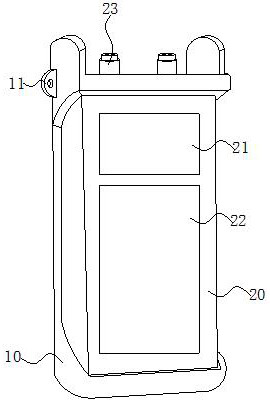
  • An optical time domain reflectometer and its positioning method for communication optical fibers between 5G base stations
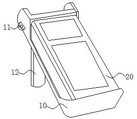
  • An optical time domain reflectometer and its positioning method for communication optical fibers between 5G base stations
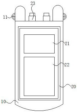
  • An optical time domain reflectometer and its positioning method for communication optical fibers between 5G base stations

Examples


Embodiment Construction

[0039] The following will be combined with the accompanying drawings in the embodiments of the present invention, the technical solution in the embodiments of the present invention will be described clearly and completely, it is clear that the embodiments described are only a part of the embodiment of the present invention, not all embodiments. Based on embodiments in the present invention, all other embodiments obtained by those of ordinary skill in the art without making creative work, are within the scope of protection of the present invention.

[0040] Further, the element of the present invention is referred to as "fixed to" or "disposed to" another element, which may be directly on another element or may also be present in the center of the element. When one component is considered to be "connected" to another component, it can be directly connected to another component or may also have a centering component. As used herein, the terms "vertical", "horizontal", "left", "right...


PUM


Abstract

An optical time domain reflectometer and its positioning method for communication optical fibers between 5G base stations, which relate to the technical field of communication networks, include a reflector body and a casing, the rear end of the casing is rotatably connected to a rotating plate, and the rotating plate is close to the casing A mounting groove is provided at one end of the rotating plate, a shielding plate is installed on the rotating plate, a fixed rod is fixedly connected in the mounting groove, and a set block is rotatably fitted on the fixed rod, and the end of the set block far away from the fixed rod is connected with the The baffle plate is fixedly connected, and the baffle plate is rotatably connected with the rotating plate through a sleeve block. The upper and lower ends of the baffle plate are respectively fixedly connected with arc-shaped blocks, and both sides of the baffle plate along the cable direction are fixedly connected with arc-shaped blocks. , the shielding plate located between the two arc-shaped blocks forms a limiting groove, which can reduce the bending degree of the cable, thereby realizing the protection of the cable and reducing the damage caused by the excessive bending of the cable. The problem of low detection accuracy.

Description

Technical field [0001] The present invention relates to the field of digital information transmission technology, specifically a 5G base station inter-communication optical fiber optical fiber optical fiber with optical time domain reflectometer and positioning method thereof. Background [0002] 5G network signal transmission, in the process of 5G base station and 5G terminal signal transmission, will eventually be converted into optical signal transmission, optical signal transmission medium is generally optical fiber, optical time domain reflector is through the analysis of the measurement curve, to understand the uniformity of optical fiber, defects, fractures, joint coupling and other performance of the instrument, it is based on the backscatter of light and Fresnel reverse principle of production, the use of light in the optical fiber propagation of the backscattered light to obtain attenuation information, It can be used to measure the location of fiber failure points and ...

Claims


Application Information

Patent Timeline
Patent Type & Authority Patents(China)
IPC IPC(8): H04B10/071H04B10/079H04B10/2575
CPCH04B10/071H04B10/0791H04B10/2575
Inventor 高原郭洋王平王景曹江王晓楠杨思明马宁
Owner 中国人民解放军军事科学院战争研究院
Learn More